Tuesday 28 October 2014

FTDI all-in-one serial converter, programmer, switch


FTDI all-in-one
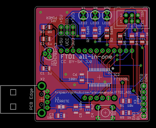
FTDI all-in-one PCB layout.

There are a multitude of FTDI converters and breakout boards available but none of them exactly fitted my needs so this is my version tuned to suit my requirements. I'm publishing the design files in the hope they are useful for others. Like the Sparkfun FTDI Basic Breakout and the Adafruit FTDI Friend it uses the FTDI FT232R but there are a number of differences, for instance it has a USB type A connector to plug directly into a USB host port.

Serial converter

The FTDI AIO provides a serial adaptor with the standard 6 pin FTDI pinout (TX, RX, CTS, DTR, VCC, and GND). A jumper block enables the VCC pin to be switched between +3.3V and +5V. A separate jumper enables the logic levels of the TX, RX, DTR and CTS signals to be set for +3.3V or +5V operation. The Sparkfun FTDI Basic Breakout can also be switched between +3.3V and +5V operation but does not allow for independent selection of VCC and the logic levels. This means when the Sparkfun FTDI Basic is set for +3.3V operation it's not compatible with the standard FTDI cables, which always supply +5V to the VCC pin. Whether that's a good thing or a bad thing depends on your needs; the FTDI AIO gives you both options.

AVR ISP programmer

Programming AVR microcontrollers, even with just a small bootloader, can be painfully slow and normally I'd use the AVR Dragon. There are situations however where it would be useful to have a low-cost USB programmer. A bit-banging AVR programmer is easily made and Adafruit has an excellent tutorial which explains how to do this.The FTDI all-in-one makes this convenient by providing the standard AVR ISP header. The defacto AVR standard is that the VCC pin is set to the same voltage as the logic-level signals. Unfortunately this practice isn't followed by +3.3V Arduino boards which always set VCC to +5V. For the widest compatibility the AVR ISP VCC pin can be set to either +3.3V or +5V with the logic levels of the !RESET, MISO, MOSI and SCK signals independently configured to either  +3.3V or +5V.

On-board +3.3V voltage regulator

One of the features of the FT232R is that it has a built-in +3.3V regulator. This was used by older Arduinos to provide a +3.3V supply. However the current capability is limited to just 50mA which in many cases is not sufficient to power a microcontroller and all of its peripherals. The FTDI all-in-one can include an on-board voltage regulator with 250mA current output which should be sufficient to power an Arduino and several shields.

Auxiliary switch and LED

One of the key features I wanted was the ability to add an auxiliary switch and LED to the Raspberry Pi. Although the Pi has GPIO the AuroraWatchNet magnetometers normally have a radio fitted to this connector, which prevents it being easily used for other purposes. I worked around this by wiring a switch and LED to a Sparkfun FTDI Basic Breakout but I wanted a single PCB which plugged directly into one of the Pi's USB sockets.

Why would you want a switch? There are probably many uses. Mine is that I run one of the AuroraWatchNet magnetometers and I wanted a way to conveniently signal when I am going to cut the grass, or make some other magnetic disturbance in the garden.The data logging software, which runs on a Raspberry Pi, checks for the existence of a file which signals data quality might be bad. When the file is present data is logged to a separate set of files which aren't used by the AuroraWatch UK alerts system. While it's no bother for me to create the file by logging into the Pi I needed something simpler for other members of the family, so I wanted to wire up a switch. A separate daemon monitors the serial port to detect if the switch is pressed, if so the LED is turned on and the semaphore file created. If the switch is pressed again the file is removed and the LED turned off. The LED actually tracks the state of the file being present so it is possible to override the monitor process by creating or removing the semaphore file by other means.

Breakout board

All of the GPIO pins from the FTDI FT232R are conveniently broken out to pads spaced at 0.1" pitch. Also included are pads for the filtered +5V supply obtained from USB and +3.3V from the on-board regulator (if fitted, otherwise from the FT232R's built-in regulator).

Why use the FT232R?

Given the recent controversy regarding FTDI and Windows drivers you might wonder why I am using the FT232R instead of some other device. I'd probably prefer to use the Microchip MCP2200 USB UART converter for this application as it works well with my Calunium Arduino clone and it is available in a SOIC package which is easier to work with at home. Unfortunately its not possible to read the CTS line with the USB CDC driver which rules it out.

Open-source hardware

The Eagle PCB design files are available on Github and are licensed under the Creative Commons Attribution-ShareAlike 3.0 (CC BY-SA 3.0) license.

The PCB layout is not yet tested, although I did breadboard and test all of the functionality. I'll be sending the design off for manufacture in the next few days, it's likely I'll have a few boards spare.

Update: the first boards have been assembled and tested; all features work as planned. The bit-banging AVR ISP programmer is even slower than I feared, taking about 10 minutes to read the 4Kb EEPROM on the Atmel ATmega1284P on one of my Calunium boards.
Friday 12 September 2014

Why Kp is a poor indicator for auroral alerts

What is Kp?

Kp is a an index to represent the planetary geomagnetic activity. The name originates from "planetarische Kennziffer" (German for planetary index). It has 10 main levels, numbered from 0 (no geomagnetic activity) to 9 (extreme geomagnetic activity). The intermediate ranges are subdivided with a + or - suffix, making 28 levels in total (0, 0+, 1-, 1, 1+, 2-, 2, 2+, ... 8, 8+, 9-, 9).

The Kp index is calculated for three-hourly intervals, beginning at UT midnight. To calculate Kp the daily "solar-quiet" (Sq) variation is removed from the measurements of magnetic field strength. Then the difference between the largest and smallest values is computed. By looking up the difference in a conversion table the local K index can be found. Stations at different latitudes (or more properly magnetic latitudes) have different conversion tables.

There is a pronounced daily variation in the K index at a single station, with intervals close to local midnight being substantially more disturbed in comparison with those centered on local noon; see http://www-app3.gfz-potsdam.de/kp_index/conv_tab.html. For this reason the planetary Kp index is computed from magnetic variations recorded by 13 magnetometers located around the world.

Why Kp is a poor indicator for auroral alerts

The Kp index only indicates geomagnetic activity within a 3 hour interval, which is too long to be useful for auroral alerts. Geomagnetic conditions can have recovered to a calm state long before the next Kp index is computed. This is particularly true for aurora caused by a substorm, as the entire substorm cycle (including the growth, expansion and recovery phases) is typically 2 to 4 hours duration; see http://www.ann-geophys.net/29/2031/2011/angeo-29-2031-2011.html.

It must also be noted that the official Kp values are not available in real-time. Not only must the data from the 13 stations be collected the quiet-day curves for each of the magnetometers must be calculated for that calendar month, a process which cannot begin until the month ends. Therefore any references to Kp for the current month will be to unofficial estimates. The most reliable estimate of Kp is probably obtained from NOAA, which is derived from a worldwide distribution of magnetometers, see http://www.swpc.noaa.gov/products/planetary-k-index.

In summary: Kp is not available in real-time. The 3 hour interval means current auroral activity may be much lower than an estimated Kp value suggests.

Estimated Kp can differ significantly from the local K index

As noted above, the pronounced daily variation of the K index means that there can be considerable difference between the average planetary geomagnetic activity (Kp) and that observed locally (K). The plot below shows the difference between the local K index measured by the British Geological Survey magnetometer at Eskdalemuir and Kp.

Difference between Eskdalemuir local K index and Kp
Difference between K index measured at Eskdalemuir and Kp.

The plot shows that in general there is good agreement but at certain times the K index can be higher or lower than Kp.

In summary: global measurements of Kp are not always valid indications of  regional geomagnetic activity.

What measurements should be used?

One of the better measurements is using the K index as long as it is from a nearby magnetometer or one on a similar geomagnetic longitude. It is still limited by the 3 hour resolution of the K index so it will not always be accurate for real-time measurements.

An alternative measurement is to consider the rate of change of the magnetic field, commonly referred to by its mathematical notation dB/dt ("D B by D T"). This measurement is of particular interest to operators of pipelines and long power distribution networks since it indicates the levels of geomagnetically-induced currents which might be expected. British Geological Survey publish real-time dB/dt measurements. These measurements require magnetically quiet sites as human interference is likely to cause sudden spikes with a high dB/dt value, limiting its usefulness to observatory measurements.

AuroraWatch UK publishes a real-time auroral activity measurement. It is the H component deviation, which is the difference between the current H component magnetic field strength and the expected value for the time of day taken from the "quiet-day curve". Unlike Kp this measurement is computed hourly and so can indicate a return to low activity values sooner than Kp. An accurately fitted quiet day curve is required to make the deviation measurement.

Data credits

Eskdalemuir K indices were downloaded from the British Geological Surveyhttps://www.bgs.ac.uk/discoverymetadata/13480122.html. Kp data was downloaded from GFZ-Potsdamftp://ftp.gfz-potsdam.de/pub/home/obs/kp-ap/tab/.

Saturday 17 May 2014

Calunium v2.1a

I've made a few minor improvements to the Calunium design, partly to satisfy compatibility between Calunium and Arduino shields and partly to fix a few minor hardware errors.

Disconnect VCC from the ISP header

The ISP header is a 6 pin male header which can be used to program the microcontroller, such as to upload the bootloader. On Calunium the VCC pin of this header is wired to the same supply voltage used by the microcontroller, ie +3.3V or +5V depending upon the operating volatge selected. This makes sense, especially when used when programmers such as Atmel's AVR Dragon which use the pin to set the HIGH voltage level on the SCK and MOSI control lines. Unfortunately it seems that on Arduino devices (such as the Ethernet shield) this pin is always wired to +5V. This is true even for the latest hardware versions which should be aware of the operating voltage via the IOREF pin. To avoid the possibility of connecting the +3.3V and +5V supplies I added a jumper. For normal operation the shunt can be omitted. When using an ISP header programmer that needs to know the operating voltage a shunt can be added.

Pull-down resistor on D13 FET

Calunium uses a field-effect transistor (FET) to switch on the D13 LED. This is to avoid load on the D13 SCK line when it is used for SPI communications. I learnt this trick from Freetronics who do something similar with their range of clones. In normal use, when D13 is an output, everything works fine. However, when it is an input, such as during RESET state or bootloader programming, the FET gate can float to potential such that the LED is switched on. A 1 megaohm pull down resistor connected to D13 is sufficient to prevent this happening without loading the SCK line. It also helps prevent damage by electrostatic discharge. The latest Calunium design now has room to add this 1 megaohm resistor. On older boards an 0805 surface mount resistor can be fitted between the gate and source of the 2N7000 FET, or alternatively between the D13 and adjacent ground pin.

Auto-reset behaviour corrected for MCP2200 USB interface

I recently added the option of fitting the MCP2200 USB-serial interface. Despite suggestions to the contrary this useful USB  device can automatically reset the Arduino when the device is opened. This auto-reset behaviour as it is known is used to activate the bootloader when uploading sketches. The intention was that auto-reset could be disabled by removing a shunt from the AUTO RESET jumper. Unfortunately an error in the schematic meant that auto-reset could only be disabled when using the FTDI interface, not the MCP2200 option. The latest version corrects this error.

Silkscreen label corrected

On Calunium v2.1 a jumper was added to select FTDI or USB power. Due to a rotation of the component the correct position for the shunt is opposite to that indicated by the silkscreen label. The latest version corrects the text.

Open source

The Eagle PCB design files for Calunium are available on Github and are licensed under the Creative Commons Attribution-ShareAlike 3.0 Unported License. Files to allow Calunium to be used with the Arduino 1.0 IDE are available on  Github and are licensed under the Gnu General Public License v2.

Monday 24 March 2014

Power over ethernet (PoE) magnetometer and cloud detector

Combined magnetometer and cloud detector
Combined magnetometer and cloud detector.


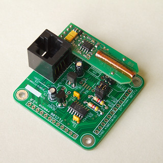
To improve the performance and stability of the AuroraWatchNet magnetometers I recently began experimenting with a power over ethernet (PoE) version. With restrictions on power consumption lifted considerable performance improvements are possible. As a result I have developed the magnetometer hardware specifically to support a power over ethernet version. Another instrument I've been developing is a cloud detector. This too should benefit from a power over ethernet version. One problem I encountered was with dew settling on the sensor but fitting a heater is incompatible with battery-powered operation. Since both the magnetometer and cloud detector use almost the same hardware I decided to design an Arduino-compatible 'shield' that could be used to support both systems.

Combined magnetometer and cloud detector hardware

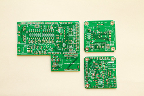
Combined magnetometer and cloud detector PCBs
Printed circuit boards for the sensor shield (left), the IR or humidity sensor (top right)
and fluxgate magnetometer (bottom right). Click for annotated version.
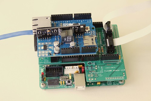
The complete system requires six circuit boards (five for the wireless version). The first is the microcontroller board, I use my Calunium Arduino clone. I hope that in future it will be possible to use an off-the-shelf Arduino Mega2560 instead but the current firmware relies on Calunium's real-time clock to generate the hardware interrupts which control the sampling interval. There is also a sensor shield, the Arduino Ethernet shield (omitted on the battery-powered wireless version), and one board for each of the sensors (fluxgate magnetometer, IR temperature and humidity).

The sensor shield is based on the existing design and retains the option of battery-powered operation with radio communication. The magnetometer sensor and analogue-to-digital converter must be powered at 5V, which requires a level-shifting circuit when the microcontroller is powered from 3.3V, which is the case when operating from batteries. For power over ethernet use the microcontroller must also operate at 5V for compatibility with the Arduino Ethernet shield so the level shifting is not required. It is kept however as it provides buffering between the two circuit boards; 1.5m is a considerable distance for an I2C bus. The cloud detector uses a non-contact infra-red temperature sensor operating at 3.3V so a level-shifting circuit is required for PoE operation where the microcontroller is connected to 5V. (I've ignored the fact that a 5V version of the sensor exists since it isn't readily available in the UK). The sensor shield allows a humidity sensor to be connected so that estimates of the clear sky and cloudy sky temperatures can be made. As before, an on-board LM61 temperature sensor monitors the system temperature. The new sensor shield also adds a header to fit an Embedded Adventures lightning sensor module. I don't have one of these at the moment so I can't be certain it will work and there is no software support for it in the existing firmware. Fitting it at the same time as the cloud detector sensors will require long break-away headers to be soldered to the bottom of the lightning sensor module.

Fluxgate magnetometer sensor PCB
Fluxgate magnetometer sensor mounted on its sensor PCB.
Click for annotated version.

The fluxgate sensor is fitted on its own PCB which contains the analogue to digital converter. For PoE operation a linear voltage regulator is used to convert from 9V to the 5V supply it requires. For battery operation a MAX619 DC-DC charge pump boosts the battery voltage to 5V. Almost all of the temperature variation can be removed by placing the PCB at the bottom of a 1m length of soil pipe. The pipe is buried to a depth of 0.85m with its axis vertical. In the magnetometer-only system the microcontroller, sensor shield and ethernet shield (or batteries for the wireless version) are fitted onto a wooden frame to hold them into the top part of the tube. Positioning the rest of the system away from the fluxgate sensor helps to avoid unwanted effects from any ferro-magnetic components (such as the batteries), it also aids access and enables wireless data transmission.

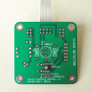
Humidity sensor PCB
Honeywell HIH6131 humidity sensor mounte on its sensor PCB.
The same PCB design is also used for the MLX90614 IR temperature sensor.
Click for annotated version.

The enclosure design used for the magnetometer isn't suitable for the cloud detector so the prototype cloud detector used a standard IP65 rated box, with the IR temperature sensor pointing upwards to view the sky. The humidity sensor was fitted above a breather hole in the bottom of the box. This concept will continue to be used for the cloud detector; the IR temperature sensor and humidity sensor are fitted to separate PCBs in the top and bottom of the box. To minimise costs the IR temperature and humidity sensors use the same PCB design. The mechanical design of the cloud detector part is something I'd like to improve upon, particularly to reduce the number of PCBs used. However the differing sensor requirements may prevent this.

For a combined system I plan to use the soil pipe to house the fluxgate sensor but locate the rest of the electronics in a separate box following the design of the prototype cloud detector.

Does it work?

I've not yet deployed a system outside but testing indicates the new printed circuit boards work as intended when used in power over ethernet mode. Battery-powered operation on this new version has not yet been tested.

Design files

The design files (hardware, firmware and software) are open source and can all be downloaded from the Github repository. A PDF version of the user manual describing how to construct and operate the magnetometer can be downloaded from http://aurorawatch.lancs.ac.uk/manual.pdf. At the time of writing only instructions to build the original FLC100 shield are included. Instructions to build the combined sensor shield described above will be added in due course.


Wednesday 12 February 2014

Performance comparison of power over ethernet (PoE) and battery magnetometers

Introduction

I've been working to improve the performance and stability of the AuroraWatchNet magnetometers. It's apparent that both measurement noise and stability are considerably improved when the sensor is powered continually. Unfortunately with the sensor powered continually the batteries last for only a few weeks. I have therefore been testing a power over ethernet (PoE) version of the magnetometer. The hardware is essentially the same but the addition of the Arduino Ethernet shield requires the microcontroller to operate from 5V. Operating voltage is easily changed on my Calunium microcontroller board. With the power restrictions lifted the sampling interval can also be reduced. The test system has been operating reliably for almost two months, sampling every 5 seconds. With some minor configuration changes sampling every second is possible although I am not convinced the trade-off in measurement noise is worthwhile.

Performance comparison

Below is a plot comparing one hour of data from the new power over ethernet system with two of the existing battery-powered wireless models already in operation. The PoE system is on the same site as LAN1 but located nearer parked cars. I chose this period because it was free of man-made disturbances. I adjusted the baselines so that the plots overlap.Only the H component of the magnetic field is shown.

Power over ethernet compared with existing AWN magnetometers
Click for larger version.

The graph shows that the power over ethernet version has much smaller measurement errors; it can probably operate with ~0.1nT accuracy compared to ~10nT for the battery-powered version. It's such an improvement that I found the measurement accuracy was being limited by the available resolution of the analogue-to-digital converter. The battery-powered versions derive the sample value from the median of 15 samples (taken as a burst over 4 seconds) to reduce noise. To improve the resolution for the PoE version it operates by taking the mean of 15 samples. Further improvement to the resolution may be possible by taking advantage of the programmable gain amplifier that is built into the analogue-to-digital converter.

Let's see how it compares against some observatory-grade measurements. The plot below shows the same interval but this time uses data from the British Geological Survey magnetometers at Eskdalemuir and Hartland. I obtained the data from the SAMNET data archive at Lancaster University, where the data has already been converted into HEZ magnetic coordinates. AuroraWatchNet also operates with HEZ magnetic coordinates, although usually the E and Z sensors are not present. As before, the baselines have been adjusted so that the plots overlap.


PoE magnetometer compared with BGS magnetometers
Click for larger version.


The similarity between the different traces is striking. Some differences are to be expected since Eskdalemuir is approximately 140km north of Lancaster and Hartland is 350km SSW of Lancaster. This interval is interesting because it shows Pi2 pulsations, starting at about 01:15 and ending around 01:30. The period of the pulsations are about 90 to 120 seconds.

Conclusions

For a home-built citizen-science magnetometer which probably costs 25 times less than its observatory grade cousin I'm very happy with its performance. The detection of Pi2 pulsations means a low-cost magnetometer can now notify of substorm onset, not just the arrival of geomagnetic storms. A network of such devices has interesting possibilities for the study of magnetic field line resonances.

You might wonder why anyone would want to buy an observatory grade instrument, there are good reasons. At present I am relying on the sensor manufacturer's calibration, whilst an observatory grade instrument would be supplied with an official calibration certificate. The observatory instrument would also have better long-term baseline stability, lower temperature variation and higher cadence. Calibration is an issue I hope to tackle at a later date. For space-weather monitoring only short-term variations are of interest and
the better performance provided by an observatory system may not be needed.

Data credits

The Sub-Auroral Magnetometer Network data (SAMNET) is operated by the Space Plasma Environment and Radio Science (SPEARS) group, Department of Physics, Lancaster UniversityHartland and Eskdalemuir data is provided courtesy of the British Geological Survey.