Showing posts with label Calunium. Show all posts

Saturday, 17 May 2014

Calunium v2.1a

I've made a few minor improvements to the Calunium design, partly to satisfy compatibility between Calunium and Arduino shields and partly to fix a few minor hardware errors.

Disconnect VCC from the ISP header

The ISP header is a 6 pin male header which can be used to program the microcontroller, such as to upload the bootloader. On Calunium the VCC pin of this header is wired to the same supply voltage used by the microcontroller, ie +3.3V or +5V depending upon the operating volatge selected. This makes sense, especially when used when programmers such as Atmel's AVR Dragon which use the pin to set the HIGH voltage level on the SCK and MOSI control lines. Unfortunately it seems that on Arduino devices (such as the Ethernet shield) this pin is always wired to +5V. This is true even for the latest hardware versions which should be aware of the operating voltage via the IOREF pin. To avoid the possibility of connecting the +3.3V and +5V supplies I added a jumper. For normal operation the shunt can be omitted. When using an ISP header programmer that needs to know the operating voltage a shunt can be added.

Pull-down resistor on D13 FET

Calunium uses a field-effect transistor (FET) to switch on the D13 LED. This is to avoid load on the D13 SCK line when it is used for SPI communications. I learnt this trick from Freetronics who do something similar with their range of clones. In normal use, when D13 is an output, everything works fine. However, when it is an input, such as during RESET state or bootloader programming, the FET gate can float to potential such that the LED is switched on. A 1 megaohm pull down resistor connected to D13 is sufficient to prevent this happening without loading the SCK line. It also helps prevent damage by electrostatic discharge. The latest Calunium design now has room to add this 1 megaohm resistor. On older boards an 0805 surface mount resistor can be fitted between the gate and source of the 2N7000 FET, or alternatively between the D13 and adjacent ground pin.

Auto-reset behaviour corrected for MCP2200 USB interface

I recently added the option of fitting the MCP2200 USB-serial interface. Despite suggestions to the contrary this useful USB  device can automatically reset the Arduino when the device is opened. This auto-reset behaviour as it is known is used to activate the bootloader when uploading sketches. The intention was that auto-reset could be disabled by removing a shunt from the AUTO RESET jumper. Unfortunately an error in the schematic meant that auto-reset could only be disabled when using the FTDI interface, not the MCP2200 option. The latest version corrects this error.

Silkscreen label corrected

On Calunium v2.1 a jumper was added to select FTDI or USB power. Due to a rotation of the component the correct position for the shunt is opposite to that indicated by the silkscreen label. The latest version corrects the text.

Open source

The Eagle PCB design files for Calunium are available on Github and are licensed under the Creative Commons Attribution-ShareAlike 3.0 Unported License. Files to allow Calunium to be used with the Arduino 1.0 IDE are available on  Github and are licensed under the Gnu General Public License v2.

Monday, 24 March 2014

Power over ethernet (PoE) magnetometer and cloud detector

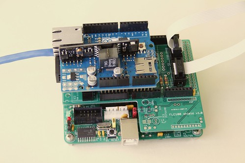
Combined magnetometer and cloud detector
Combined magnetometer and cloud detector.


To improve the performance and stability of the AuroraWatchNet magnetometers I recently began experimenting with a power over ethernet (PoE) version. With restrictions on power consumption lifted considerable performance improvements are possible. As a result I have developed the magnetometer hardware specifically to support a power over ethernet version. Another instrument I've been developing is a cloud detector. This too should benefit from a power over ethernet version. One problem I encountered was with dew settling on the sensor but fitting a heater is incompatible with battery-powered operation. Since both the magnetometer and cloud detector use almost the same hardware I decided to design an Arduino-compatible 'shield' that could be used to support both systems.

Combined magnetometer and cloud detector hardware

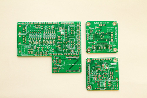
Combined magnetometer and cloud detector PCBs
Printed circuit boards for the sensor shield (left), the IR or humidity sensor (top right)
and fluxgate magnetometer (bottom right). Click for annotated version.
The complete system requires six circuit boards (five for the wireless version). The first is the microcontroller board, I use my Calunium Arduino clone. I hope that in future it will be possible to use an off-the-shelf Arduino Mega2560 instead but the current firmware relies on Calunium's real-time clock to generate the hardware interrupts which control the sampling interval. There is also a sensor shield, the Arduino Ethernet shield (omitted on the battery-powered wireless version), and one board for each of the sensors (fluxgate magnetometer, IR temperature and humidity).

The sensor shield is based on the existing design and retains the option of battery-powered operation with radio communication. The magnetometer sensor and analogue-to-digital converter must be powered at 5V, which requires a level-shifting circuit when the microcontroller is powered from 3.3V, which is the case when operating from batteries. For power over ethernet use the microcontroller must also operate at 5V for compatibility with the Arduino Ethernet shield so the level shifting is not required. It is kept however as it provides buffering between the two circuit boards; 1.5m is a considerable distance for an I2C bus. The cloud detector uses a non-contact infra-red temperature sensor operating at 3.3V so a level-shifting circuit is required for PoE operation where the microcontroller is connected to 5V. (I've ignored the fact that a 5V version of the sensor exists since it isn't readily available in the UK). The sensor shield allows a humidity sensor to be connected so that estimates of the clear sky and cloudy sky temperatures can be made. As before, an on-board LM61 temperature sensor monitors the system temperature. The new sensor shield also adds a header to fit an Embedded Adventures lightning sensor module. I don't have one of these at the moment so I can't be certain it will work and there is no software support for it in the existing firmware. Fitting it at the same time as the cloud detector sensors will require long break-away headers to be soldered to the bottom of the lightning sensor module.

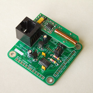
Fluxgate magnetometer sensor PCB
Fluxgate magnetometer sensor mounted on its sensor PCB.
Click for annotated version.

The fluxgate sensor is fitted on its own PCB which contains the analogue to digital converter. For PoE operation a linear voltage regulator is used to convert from 9V to the 5V supply it requires. For battery operation a MAX619 DC-DC charge pump boosts the battery voltage to 5V. Almost all of the temperature variation can be removed by placing the PCB at the bottom of a 1m length of soil pipe. The pipe is buried to a depth of 0.85m with its axis vertical. In the magnetometer-only system the microcontroller, sensor shield and ethernet shield (or batteries for the wireless version) are fitted onto a wooden frame to hold them into the top part of the tube. Positioning the rest of the system away from the fluxgate sensor helps to avoid unwanted effects from any ferro-magnetic components (such as the batteries), it also aids access and enables wireless data transmission.

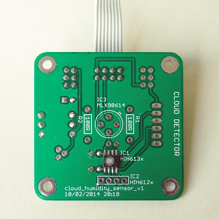
Humidity sensor PCB
Honeywell HIH6131 humidity sensor mounte on its sensor PCB.
The same PCB design is also used for the MLX90614 IR temperature sensor.
Click for annotated version.

The enclosure design used for the magnetometer isn't suitable for the cloud detector so the prototype cloud detector used a standard IP65 rated box, with the IR temperature sensor pointing upwards to view the sky. The humidity sensor was fitted above a breather hole in the bottom of the box. This concept will continue to be used for the cloud detector; the IR temperature sensor and humidity sensor are fitted to separate PCBs in the top and bottom of the box. To minimise costs the IR temperature and humidity sensors use the same PCB design. The mechanical design of the cloud detector part is something I'd like to improve upon, particularly to reduce the number of PCBs used. However the differing sensor requirements may prevent this.

For a combined system I plan to use the soil pipe to house the fluxgate sensor but locate the rest of the electronics in a separate box following the design of the prototype cloud detector.

Does it work?

I've not yet deployed a system outside but testing indicates the new printed circuit boards work as intended when used in power over ethernet mode. Battery-powered operation on this new version has not yet been tested.

Design files

The design files (hardware, firmware and software) are open source and can all be downloaded from the Github repository. A PDF version of the user manual describing how to construct and operate the magnetometer can be downloaded from http://aurorawatch.lancs.ac.uk/manual.pdf. At the time of writing only instructions to build the original FLC100 shield are included. Instructions to build the combined sensor shield described above will be added in due course.


Wednesday, 12 February 2014

Performance comparison of power over ethernet (PoE) and battery magnetometers

Introduction

I've been working to improve the performance and stability of the AuroraWatchNet magnetometers. It's apparent that both measurement noise and stability are considerably improved when the sensor is powered continually. Unfortunately with the sensor powered continually the batteries last for only a few weeks. I have therefore been testing a power over ethernet (PoE) version of the magnetometer. The hardware is essentially the same but the addition of the Arduino Ethernet shield requires the microcontroller to operate from 5V. Operating voltage is easily changed on my Calunium microcontroller board. With the power restrictions lifted the sampling interval can also be reduced. The test system has been operating reliably for almost two months, sampling every 5 seconds. With some minor configuration changes sampling every second is possible although I am not convinced the trade-off in measurement noise is worthwhile.

Performance comparison

Below is a plot comparing one hour of data from the new power over ethernet system with two of the existing battery-powered wireless models already in operation. The PoE system is on the same site as LAN1 but located nearer parked cars. I chose this period because it was free of man-made disturbances. I adjusted the baselines so that the plots overlap.Only the H component of the magnetic field is shown.

Power over ethernet compared with existing AWN magnetometers
Click for larger version.

The graph shows that the power over ethernet version has much smaller measurement errors; it can probably operate with ~0.1nT accuracy compared to ~10nT for the battery-powered version. It's such an improvement that I found the measurement accuracy was being limited by the available resolution of the analogue-to-digital converter. The battery-powered versions derive the sample value from the median of 15 samples (taken as a burst over 4 seconds) to reduce noise. To improve the resolution for the PoE version it operates by taking the mean of 15 samples. Further improvement to the resolution may be possible by taking advantage of the programmable gain amplifier that is built into the analogue-to-digital converter.

Let's see how it compares against some observatory-grade measurements. The plot below shows the same interval but this time uses data from the British Geological Survey magnetometers at Eskdalemuir and Hartland. I obtained the data from the SAMNET data archive at Lancaster University, where the data has already been converted into HEZ magnetic coordinates. AuroraWatchNet also operates with HEZ magnetic coordinates, although usually the E and Z sensors are not present. As before, the baselines have been adjusted so that the plots overlap.


PoE magnetometer compared with BGS magnetometers
Click for larger version.


The similarity between the different traces is striking. Some differences are to be expected since Eskdalemuir is approximately 140km north of Lancaster and Hartland is 350km SSW of Lancaster. This interval is interesting because it shows Pi2 pulsations, starting at about 01:15 and ending around 01:30. The period of the pulsations are about 90 to 120 seconds.

Conclusions

For a home-built citizen-science magnetometer which probably costs 25 times less than its observatory grade cousin I'm very happy with its performance. The detection of Pi2 pulsations means a low-cost magnetometer can now notify of substorm onset, not just the arrival of geomagnetic storms. A network of such devices has interesting possibilities for the study of magnetic field line resonances.

You might wonder why anyone would want to buy an observatory grade instrument, there are good reasons. At present I am relying on the sensor manufacturer's calibration, whilst an observatory grade instrument would be supplied with an official calibration certificate. The observatory instrument would also have better long-term baseline stability, lower temperature variation and higher cadence. Calibration is an issue I hope to tackle at a later date. For space-weather monitoring only short-term variations are of interest and
the better performance provided by an observatory system may not be needed.

Data credits

The Sub-Auroral Magnetometer Network data (SAMNET) is operated by the Space Plasma Environment and Radio Science (SPEARS) group, Department of Physics, Lancaster University. Hartland and Eskdalemuir data is provided courtesy of the British Geological Survey.


Saturday, 19 October 2013

Cloud detector: a review of progress so far

The hardware

My cloud detector has been running outside for over 5 months now. Overall I'm very pleased with how it works. The battery-powered hardware is based on the AuroraWatchNet magnetometer design, which uses my own Calunium microcontroller development board. The remote sensor board and fluxgate sensor are omitted. I've added a Melexis MLX90614 non-contact infra-red thermometer to measure the sky temperature. Clear skies should give low temperatures whilst clouds are expected to have warmer temperatures, although still colder than the ambient temperature. The MLX90614 also outputs the sensor temperature, which should be close to the ambient temperature. I also added a Honeywell HIH-6131-021 humidity sensor which has an I2C interface. Do not confuse with the similar sounding version which has an SPI interface! The HIH-6130 also provides and ambient temperature measurement. To avoid direct contact with water the humidity sensor is placed at the bottom of the enclosure with a hole underneath to expose it to air. This hole also functions as a breather hole and ensures that the internal pressure matches atmospheric pressure. Since this hole was drilled there have not been any more incidents of water ingress.

The Calunium board is running a firmware is a modified version of the magnetometer firmware. It communicates with the Raspberry Pi data logger using an 868MHz radio link, with the same signed communication protocol used by AuroraWatchNet. This means I can use the data recording software from AuroraWatchNet. It also inherits the signed over-the-air firmware update capability. In principle it should be possible to combine both magnetometer and cloud detector functions in one unit.

I started off using the 90°  field-of-view version of the non-contact IR thermometer but later switched to theMLX90614ESF-DCH-000-TU-ND variant which features a 12° field of view. Its greater height meant it was easier to fit into the cable grommet housing. However I think the FOV is too narrow and I plan to switch back to the original sensor when I have time.

Data processing

The data processing and plotting now uses the auroraplot library for Python, which I developed to process the AuroraWatchNet magnetometer data. On the graphs I plot the sky temperature measured by the non-contact IR thermometer and the ambient temperature measured by the humidity sensor. For monitoring purposes I also plot the sensor temperature of the IR thermometer (marked as "detector temperature"); this should be similar to the ambient temperature but its exposed position makes it more likely to undergo solar heating and radiative cooling. For good measure I also plot the system temperature, which is measured by an LM61 temperature sensor connected to the ATmega1284P's analogue to digital converter. This measurement is noisy but useful to check the system doesn't overheat on sunny summer days.

The plan is to estimate the upper and lower bounds that I would expect for the sky temperature, and from that derive an estimate of the cloud cover. I initially expected that with complete cloud cover the sky temperature would match that the lifted condensation level, which I estimate using the ambient temperature and relative humidity. I soon saw temperatures higher than the LCL temperature. Research literature indicates that the clouds can act as a mirror at long IR wavelengths and thus the expected temperature should include an effect of ground temperature too. On the plots this is shown as the effective cloud temperature. The clear sky temperature is derived from results found in research literature but none of the equations tried so far have been a great match. Other researchers have fitted parameters for their specific location (including altitude) by comparison with visual measurements. I have yet to try this but daily measurements are made at the nearby Hazelrigg Weather Station. The graphs are too cluttered for production use but help me to understand what is happening.

Example plots

Below are a selection of plots. You can see the entire archive (from 2013-07-14) at http://aurorawatch.lancs.ac.uk/testing/cloudwatch/test2/.

cloud_detector_20130903
Cloud detector data for 2013-09-03. The asterisk (*) indicates derived parameters (ie not directly measured).
The figure above include most of the effects that can be identified. After midnight there is thick cloud, which later clears for short periods. At around 0300 UT I think it must have rained, the sky temperature is almost identical to the detector temperature and the variability is much reduced. Whilst the sensor is wet no sensible conclusions about cloud cover can be drawn. At about 0700 UT the sensor clears of water and the sky temperature falls indicating clearer skies. The rest of the day is dry, with heavy cloud cover until 1400 UT. At around 1700 UT the skies are completely clear. The clear sky estimate is too low for this time. At 2000 UT the clouds return, with some clear patches.


Cloud detector, 2013-09-28
Cloud detector data for 2013-09-28 showing the effect of clear skies.
The figure above shows an almost completely cloud-free day. The higher variability in the sky temperature measurements between 1200-1600 UT corresponds to similar effects in the humidity data (shown below); both are direct measurements made by different sensors.

Relative humidity, 2013-09-28
Humidity data for 2013-09-28. Notice how the higher variability occurs at the same times as the sky temperature measurements.

Dew

During summer operation dew has not been a problem but now that the nights are colder I have noticed effects which I believe are due to the formation of dew on the sensor. In the first plot below the sky temperature apparently rises from around 2230 UT. The rise is smooth and during this period the ambient temperature is falling, which overnight is often a sign of clear skies. After midnight (second plot) the sky temperature increases slightly before falling sharply around 0630 UT. Sunrise on this day was 0622 UT.

Cloud detector, 2013-10-05Cloud detector, 2013-10-06
This pair of plots is believed to show dew formation on the sensor.


Conclusions

I know from the informal comparisons with visual cloud cover that I regularly make the cloud detector does generally work very well. It does not function during wet periods. As anticipated dew is becoming a problem during the colder nights and a dew heater will be required for reliable winter operation. Future development will be to add a heater, which will need a wired connection to the cloud detector. Once a wired connection is made the radio link appears superfluous so I plan to investigate the options for power-over-ethernet. The Arduino ethernet shield is one possibility, although its compatibility with 3.3V operation has not been established.

Monday, 20 May 2013

Cloud detector progress

Microcontroller and radio communications

To minimise the time and effort required to test the cloud detector concept I am following the approach used for the AuroraWatchNet magnetometer system and reusing as much hardware from it as possible. The MLX90614 non-contact infra-red temperature sensor is located outside. To minimise the infrastructure requirements the sensor unit is battery-powered and transmits its data over a bi-directional radio link. The sensor is controlled by one of my Calunium v2 microcontroller development boards. I'm using a pair of RFM12B radio modules operating at 433MHz to emulate a transparent serial connection. One is fitted on  the Calunium board and the other radio module is connected to a Raspberry Pi via my RFM12B shield. The Pi records the data and is responsible for uploading it for general access. I am also reusing most of the AuroraWatchNet firmware, which means I already have signed data communications and the capability to deploy over-the-air firmware updates - quite a good starting position for a new project!

Waterproofing the sensor

The biggest challenge I expect to face with this project is waterproofing the sensor. Although it is hermetically sealed there is no easy way to deploy it outside. As explained in a previous post, only a few materials are transparent to long-wave infra-red emissions and the better ones are toxic, water-soluble or expensive. I am therefore trying to avoid covering the sensor window and instead keep the electrical contacts dry. My first attempt was to drill a hole in the box and attach the sensor with silicone sealant. The mechanical fixing lacked strength and I wasn't convinced I had completely sealed around the sensor. To make matters worse I ended up with sealant on the sensor window which had to be cleaned off before it set. Another approach was required.

The new approach is to fit the sensor inside a cable gland. Before doing so I had to attach wires to the sensor connectors and insulate with heat-shrink sleeving. The result is shown below.


The next step is to fit the sensor in the cable gland before fitting the cable gland to the box.


The other end of the wires can then be soldered. For the prototype the wires are soldered to a small piece of stripboard. The stripboard has two pull-up resistors for the I2C bus and a decoupling capacitor. There is also an IDC connector to link the board to the unused JTAG interface. This was the easiest way to connect to a stock Calunium v2 board. For the lowest power operation the sensor is powered from logic-level output and I am using software I2C so all connections can be grounded when the sensor is not in use. The real-time clock on Calunium is connected the the hardware I2C interface on the microntroller and can be operated independently of the sensor.


The box and cable gland are rated IP65. Hopefully the result will be waterproof  

Results

The sensor is now deployed outside and reporting back to the Raspberry Pi base station. The transmitted packets are logged by the Raspberry Pi but as yet I don't have a convenient way to extract the ambient and object temperatures for analysis. That is the next task.


Sunday, 10 February 2013

The importance of brown-out detection

The batteries expired in one of the AuroraWatchNet test magnetometers this week. I was expecting that to happen since the magnetometer wasn't operating in its low-power mode and the battery voltage from the two 1.5V alkaline cells had been hovering around 2V for some time. The Atmel ATmega1284P microcontroller is actually powered at 3.3V using a boost power supply. What I didn't expect was for the system to not start after replacing the battery. I could tell xboot was working since the LED flashed 3 times as usual after the reset button was pressed. After that the LED stayed on but nothing else happened, not even the start-up debug messages from the serial port. I guessed the flash program memory had somehow got corrupted.

I used the AVR Dragon to extract the contents of the flash memory (avrdude -P usb -c dragon_jtag -p atmega1284p -U flash:r:flash.img:r) and compared it against the saved raw image file using the linux split and cmp commands. Sure enough, three pages of flash memory were set to 0xFF, probably from some erroneous page clear operation. Brown-out detection was disabled by the fuse settings to save power. Big mistake! What I think happened was as the voltage dipped below its valid range the microcontroller started executing random commands, including 3 SPM page clears, one of which was the first page of flash which holds the interrupt vector table. Valid execution was doomed.

What I should have done was to enable brown-out detection in the fuses, 2.7V seems the most appropriate setting for an 8MHz clock and 3.3V operation. To save power during sleeping the brown-out detection can be disabled with a call to sleep_bod_disable(). Lesson learned!

Saturday, 9 February 2013

Calunium: version 2.1

Calunium v2.1
Calunium v2.1.
Click on the image for an annotated version.

This upgrade to Calunium v2 provides several minor improvements. There is the option to fit a Microchip MCP220 UART-USB converter instead of the FTDI connector. For development purposes the MCP2200 is much more convenient than an external FTDI cable or adaptor; operation at both 3.3V and 5V is supported. For low-power battery operation the MCP2200 uses too much power so the FTDI connector option has been retained.

I find I operate Calunium almost exclusively at 3.3V. I've not been able to find any real-time clocks in a dual-in-line package that operate at 3.3V and feature battery-backup. Suitable clocks are supplied in a SOIC or smaller package. I have therefore removed the DIP footprint option for the real-time clock. The space saved has allowed me to add optional load capacitors for the crystal so that a MicroChip MCP7941x real-time clock can be used. This clock has several benefits over the popular DS1307 (or its 3.3V equivalent, the DS1338). It is cheaper, it can compensate for crystal frequency errors, it has EEPROM storage, two alarms and it also has a unique identifier. This change goes against one of the original aims of Calunium, to use through-hole components to keep it accessible to the widest possible audience. However, considering the other interesting on-board peripherals (micro-SD socket, RFM12B and MCP2200) require surface-mount soldering skills I thought this a reasonable compromise to make. The original through-hole only designs are still available for those who really do not want to use any surface-mount components.

The final improvement is that the SPI clock signal is now routed with a ground plane between it and the real-time clock crystal.

For the full list of features please see the original Calunium v2 blog post.

Calunium v2 and v2.1 PCBs
Calunium v2 (top) and v2.1 (bottom) PCBs.
Click on the image for an annotated version.

Friday, 8 February 2013

RFM12B shield for Raspberry Pi

RFM12B and Atmel ISP programmer shield for Raspberry Pi
RFM12B shield for Raspberry Pi, with integrated in-circuit serial programmer.
Click on the image for an annotated version. 

I recently described the preliminary design of a RFM12B shield for the Raspberry Pi, which used an Atmel ATmega328 to interface between the Raspberry Pi's UART and the RFM12B's SPI interface. The design also included a buffered two-channel in-circuit serial programmer (ISP) using the Raspberry Pi's general purpose I/O. The first channel is for programming the on-board ATmega328 whilst the second channel can program external microcontrollers.

The boards have now been manufactured and the first one assembled and tested. The interface to the RFM12B and the built-in AVR ISP programmer both work as designed. I have been using the Arduino environment to compile and upload the firmware to the ATmega328. The microcontroller pin mapping is identical to the Arduino Uno although the activity LED is wired to D9 since D13 is normally in use by the SPI interface. The ATmega328 operates at 3.3V and is clocked by the internal 8MHz RC oscillator. No bootloader is needed. The Github repository contains boards.txt and programmers.txt files for use with the Arduino IDE, the standard Arduino core is used.

I have been using the first board to replace a Ciseco URF radio module. The firmware for the ATmega328 incorporates my transparent serial emulation layer. This provides a Stream object to which data can be read, and written (or printed), in just the same way as HardwareSerial and SoftwareSerial objects. The same emulation layer can then be used on remote Calunium, Arduino or JeeNode boards to provide a bi-directional data stream, allowing the user to interface to the RFM12B as easily as an XRF or XBee radio module. The emulation layer transparently uses acknowledgements and retries to provide a robust channel, which is an improvement over the Ciseco XRF and URF radio modules. Alternative firmware for the RFM12B shield is easily uploaded to provide different functionality.

ISP programmer

The avrdude configuration file contains details for two GPIO programmers; gpio0 is connected to the on-board ATmega328 and gpio1 is for programming external microcontrollers. By fitting a jumper to the JP1 header the external microcontroller can be powered from the Raspberry Pi's 3.3V supply. Be sure to observe the maximum current rating for the 3.3V supply and never fit the jumper if the remote microcontroller is self-powered. The 74LVC244 buffer ensures that MCUs operating at 5V can be safely connected. Typically the high output level from the 74LVC244 buffer will be recognised as a high but it doesn't meet the worst-case specifications when the external MCU is powered from 5V.

Open source

The Eagle PCB design files for the RFM12B/ISP shield for Raspberry Pi are available on Github and are licensed under the Creative Commons Attribution-ShareAlike 3.0 Unported License. The RF12 transparent serial emulation layer is also available on Github and is released under the MIT license.

Errata

There is a connection missing on the schematic from the drain of FET Q2 to pin 5 (/RESET) on the external ISP header (X3). This connection is also missing from the PCB but can be easily fixed with a direct wire connection on the underside of the board.

Update

I've added a description of how to install and use the patched version of avrdude, http://blog.stevemarple.co.uk/2013/03/how-to-use-gpio-version-of-avrdude-on.html.

Wednesday, 30 January 2013

Transparent serial emulation for the RFM12B radio module

Introduction

For the AuroraWatchNet magnetometers that I am developing I currently use the Ciseo XRF radio module. They are based upon the pseudo-standard XBee footprint, operate at 3.3V and provide a UART interface to the microcontroller. They are easy to use but I have found the range is not always sufficient, typically limited to 60 metres of free space plus one exterior wall/window. Another commonly-used radio module is the HopeRF RFM12B transceiver, as used on the JeeNode. The RFM12B also operates at 3.3V but features an SPI interface to the microcontroller. It is available as a 2mm pitch surface-mount module, or as a 12 pin 2mm pitch DIP package.

As my Calunium v2 microcontroller development board can be fitted with a RFM12B radio module I naturally wanted to compare the performance of the RFM12B and XRF. Initial testing of the Hope RFM12B gave a usable range of 150 metres of free space after transmission through one exterior wall/window. Some of the additional range is due to using the 433MHz version of the RFM12B compared to the 868MHz operating frequency that the XRF defaults to. The range measurements were not very scientific and further work is required before meaningful conclusions can be drawn regarding the comparative ranges. However these initial results have encouraged me to investigate replacing the XRF by the RFM12B, particularly as it is both cheaper and uses less power. A comparison of the basic specifications can be found at http://blog.homelabs.org.uk/wireless-connectivity/.

As I have already deployed a few magnetometers using the Ciseco XRF module I would like to to use the RFM12B as a serial device. This would enable the existing firmware to be used with minimal changes. It would also allow the possibility of having a single firmware support both XRF and RFM12B modules.

Serial emulation

I have created a serial emulation layer for the RFM12B by deriving a class (RF12_Stream) from the Arduino Stream class. Text or binary data can then be read from or written to the RFM12B in exactly the same way as the standard Serial port. Since it is a Stream object the Streaming class (which overloads the >> and << operators) can also be used with RF12_Stream. The RF12_Stream class automatically breaks up the data to be transmitted into short packets which are sent using the Jeelab RF12 library. ACKs and retransmissions are employed to prevent losing data from dropped packets. A packet number is included to prevent duplicated data, which could otherwise occur for the case when the ACK is not received and a packet is retransmitted. The class keeps track of the number of packets sent and received, and the number of retransmissions, data which may be useful to identify the optimal channel on which to operate.

The begin() function takes different parameters to Serial.begin() and it returns a logical value to indicate whether the RFM12B has been found on the system. The user is required to call the poll() function periodically so that outgoing packets are sent and received packets processed. These are the only differences compared to sending data to the standard Arduino Serial port.

Source code for the RF12_Serial emulation can be found on Github, https://github.com/stevemarple/RF12_Stream; it is released under the MIT license. An example sketch is included which echoes data between the Arduino serial port and the RFM12B. When compiled for the ATtiny84 this sketch is less than 8kB so I am hopeful it can be used on the RFM12B to Raspberry Pi expansion board designed by Martin Harizanov. AsyncDelay, https://github.com/stevemarple/AsyncDelay, and CircBuffer, https://github.com/stevemarple/CircBuffer, are also required.

Calunium uses INT2 for the interrupt from the RFM12B which is not supported by the JeeLabs version of the RF12 library so I am currently using a modified version. Source for this version is also available on Github, https://github.com/stevemarple/RF12. It is intended that RF12_Serial should work with both the original RF12 library and my version.

Single firmware to support RFM12B and XRF

By utilising the return value from the RF_Stream begin() function it becomes trivial to produce a single firmware which can support either the RFM12B or XRF radio modules. The trick is to create a Stream reference which is set to either Serial (for the XRF) or to rfm12b. The RFM12B_autoselect example sketch illustrates this concept.

How does it differ from RF12sio?

The RF12sio library overloads the << and >> operators so that packets can be constructed and processed easily. The user is still responsible splitting the data into packets. RF12sio is not derived from Stream so it is not possible to use the Stream pointer trick shown in the RFM12B_autoselect sketch.

Credits

Thanks to JeeLabs and JC Wippler for the RF12 library and to Arduino for the standard Arduino libraries.

Thursday, 24 January 2013

How to use the Atmel ATmega1284 (non-P version) with tools that don't support it

I found out by accident there is now an Atmel ATmega1284 microcontroller, as well as the older ATmega1284P. The first I knew was when I tried to upload the bootloader and avrdude warned of a signature mismatch:

avrdude: Device signature = 0x1e9706
avrdude: Expected signature for ATMEGA1284P is 1E 97 05
              Double check chip, or use -F to override this check

Correcting the device didn't help, avrdude doesn't recognise the ATmega1284. That could be fixed easily by creating a custom entry in $HOME/.avrduderc. I didn't bother with that since avr-gcc doesn't support the ATmega1284. At this point I was slightly worried as I had ordered a large quantity of ATmega1284 instead of the ATmega1284P.

A work-around

Fortunately there is a work-around. The two microcontrollers are essentially identically except for some small electrical differences relating to power usage and the last signature byte. Therefore code compiled for the ATmega1284P will run on the ATmega1284. If you are using avrdude to upload just add the -F command line option to force the signature check to pass.

If you use the xboot bootloader you should have no further problems after installing the bootloader since xboot doesn't check the signature bytes. Users of the Optiboot bootloader are probably not so fortunate; I believe the signature is checked - I haven't tested it since I'm now using xboot on all of my Calunium development boards.

Sunday, 13 January 2013

Magnetometer progress report

About AuroraWatchNet

I am developing a simple, low-cost, battery-powered magnetometer for auroral alerts and citizen science. It is intended to be wireless to allow easy installation, a unique feature as far as I am aware. The magnetometer uses my own Calunium micro-controller board, which is an Arduino clone based on the ATmega1284P micrcontroller. Data is sent via a radio link to a Raspberry Pi base station which will then forward the data to AuroraWatch UK. I am hoping to deploy a network of such magnetometers in 2013 to enable AuroraWatch UK users to contribute data to improve the service. If you want to track the development then follow @aurorawatchnet on Twitter. 

The first AuroraWatchNet magnetometer is currently running in my garden. The environment is not ideal as I can see disturbances from cars and even the garage door being opened but it is convenient for testing and representative of what to expect from user-contributed data. I have been comparing the results from our SAMNET magnetometers with the AuroraWatchNet prototypes and generally the results are very encouraging given the difference in cost between the two systems. Now I can plot the AuroraWatchNet magnetometer data in the standard AuroraWatch UK style, using the same Octave code. Below is a comparison of today's plots. 

AuroraWatch UK

The data is taken from SAMNET's Lancaster magnetometer. The X axis is time and the Y axis shows the magnetic field strength in the direction of magnetic North (H component) in nanotesla (nT) relative to an unrecorded baseline. This exact plot appeared on AuroraWatch UK. We would normally expect cleaner data but our Lancaster site has recently been experiencing some interference.

SAMNET data from Lancaster, as used by AuroraWatch UK

AuroraWatchNet test magnetometers

The plots below correspond to the same time interval as the plot above. The first plot is from my garden magnetometer.

AuroraWatchNet data from near Lancaster.

The Y axis again records magnetic field strength but this time it is the absolute field. This magnetometer is operating in power-saving mode, turning off the sensor when not needed. This slightly increases the noise level but I hope will give one year of operation from two D cells.

Another AuroraWatchNet magnetometer has been deployed almost adjacent to the SAMNET magnetometer we already use for AuroraWatch. In this system the magnetometer sensor is continually powered, resulting in reduced noise levels. The alignment with magnetic North is only approximate. 


AuroraWatchNet data from the Lancaster University field station.

Conclusion

The AuroraWatchNet magnetometers are sufficiently sensitive and stable to make useful contributions for auroral detection and citizen science. My experience with the garden magnetometer suggests that in many cases performance will be limited by the noise at the site, rather than the magnetometer.

Thursday, 10 January 2013

UART-USB converter for mixed 3.3V/5V operation


For some future projects I have in mind I would like to add a USB interface to my Calunium development board, rather than using the Sparkfun FTDI basic breakout board that I have been using. One of the key features is that it should work seamlessly with the jumper-selectable 3.3V or 5V operation offered by Calunium v2, which is most easily accomplished by a self-powered design; auto-reset is a bonus.

Microchip offer the MCP2200 USB interface in a choice of packages including a 20 pin SOIC package which is very convenient for home assembly of PCBs. I found conflicting information about the MCP2200 so I prototyped the above circuit to check that mixed 3.3V/5V operation was ok. VUSB (pin 17) is permanently connected to 3.3V so that the USB signalling levels are always correct. The VDD supply pin is connected to IOREF on my Calunium board, which is either 3.3V or 5V, depending on the position of the voltage selection jumper, ensuring that the logic levels for the MCP2200 match those used by the microcontroller. I also wanted to test whether the MCP2200 would auto-reset the microcontroller. The MCP2200 doesn't have a DTR output pin which is how modern Arduinos reset the microcontroller for uploading a new sketch. Fortunately the MCP2200 does have an RTS output, and as that was the method used by older Arduinos I connected that to /RESET via a 100nF capacitor.

After building the circuit and connecting it to my Ubuntu 10.04 Linux computer the MCP2200 was immediately recognised, I used the dmesg command to see this. Ubuntu automatically created the /dev/ttyACM0 device file, no configuration changes were needed at all. Using gtkterm I was able to toggle the state of the RTS pin. I then hooked up the circuit to one of my Calunium microcontroller boards and was able to upload sketches without needing to press the reset button, in both 3.3V and 5V operation modes. I haven't tested this from Windows but from what I've read on the Microchip forum I suspect it won't work due to deficiencies in the Windows driver.

The datasheet suggests that a ceramic resonator can be used instead of the crystal and load capacitors. I found it did work even though the resonator's frequency tolerance was 0.5%, not 0.25% as required by the USB specification. As I can't source any resonators which meet the specification I'll be using a 12MHz crystal.

The MCP2200 wasn't my first choice; the obvious part was the FTDI FT232RL, although I had reservations about working with an SSOP package. Further investigation revealed that 3.3V operation requires an external crystal, but to use one isn't straightforward. On first use the FT232RL must be powered from >= 4.0V and a custom utility (not openly supplied?) is needed to select the external crystal. The standard MPROG utility cannot be used for this. I am aware that the FT232RL could be powered from the USB 5V supply but I am not a big fan of powering devices simultaneously from both internal and external supplies. One of the future projects is to replace hardware which is powered from multiple sources and is very susceptible to damage from being powered up/down incorrectly.

In conclusion, this is a very useful USB converter for Linux users and for final designs. Windows users who wish to regularly upload new firmware via a bootloader may find it less useful.


Friday, 28 December 2012

Calunium: version 2

Calunium v2
Calunium version 2. Click on the image for an annotated version.

Features

  • ATmega1284P microcontroller with 128 KBytes flash memory, 16 KBytes SRAM and 4 KBytes EEPROM, SPI and I2C buses and 2 UARTS.
  • Shield-compatible with Arduino Uno revision 3, with extra I/O laid out to be compatible with Arduino Mega pins. Pin mapping is chosen for maximum compatibility with Uno.
  • Jumper-selectable 3.3 V or 5 V operation; selected voltage is available at the IOREF pin to enable shields to operate at the correct voltage.
  • I2C (SDA/SCL) mapped to dedicated SDA/SCL pins and the standard location used by the Arduino Mega but jumpers can be used to replace A4/A5 with SDA/SCL signals for compatibility with older Arduino shields.
  • Second UART (D1, D2) signals also mapped to corresponding location on Arduino Mega (TX1, RX1).
  • ISP header in standard location, allowing the Arduino ethernet/SD shield to be used.
  • D13 LED connected via FET to avoid loading D13.
  • Real-time clock (e.g, DS1307, DS1338, MCP7941x). Output square wave can be routed to D6 (INT2) or D15 (TOSC1, for input to timer/counter 2). Battery backup from CR2032 battery.
  • Micro-SD socket for additional data storage. Uses SPI bus (D11, D12, D13), chip select is D22. If card is fitted then 3.3 V operation is required.
  • Hope RFM12B radio module for communication. Uses SPI bus (D11, D12, D13), chip select is D14 and interrupt request is D6 (INT2, can be disconnected by removing a jumper). Requires 3.3 V operation; Calunium can be powered from 5 V provided that the RFM12B is not used.
  • Power from USB or FTDI connector.
  • Switches, connectors and USB socket located outside of the standard Arduino shield footprint so they do not interfere with shields and are accessible when shields are fitted.
  • Auxiliary power connector; connect your own voltage regulator or boost converter. 5 V from USB (FTDI and/or USB connector) and 3 V from RTC battery also available on the connector. For easy prototyping add your own power adaptor.
  • Auto-reset can be disabled by removing jumper.
  • Pads to fit LM61 temperature sensor.
  • Usable PCB-mounting holes.
  • JTAG header for debugging/programming.

Bootloader

Either the Optiboot or xboot bootloaders can be used. My preference is for xboot as explained in a previous blog post.

About the name

As Arduino is an Italian project, this project takes its name from the Roman name for Lancaster, Calunium, where the design of this clone originates.

Open source

Hardware
The Eagle PCB design files for Calunium are available on Github and are licensed under the Creative Commons Attribution-ShareAlike 3.0 Unported License.

Software
Files to allow Calunium to be used with the Arduino 1.0 IDE are available on  Github and are licensed under the Gnu General Public License v2.

Peripherals pin mapping

PeripheralPinFunction
LED13
Temperature sensorA6
A7
Power
Output
Real-time clock*D6/D15Square-wave output/alarm
microSD card22Card select
RFM12B radio module6
14
Interrupt request
Select
* Also uses I2C bus (20, 21).
** Also uses SPI bus (11, 12, 13).

Microcontroller pin mapping

PinArduino Uno (Atmega328P)Calunium (Atmega1284P)Arduino Mega2560 (ATmega2560)
D0PD0 (PCINT16/RXD)PD0 (PCINT24/RXD0/T3)PE0 (RXD0/PCINT8)
D1PD1 (PCINT17/TXD)PD1 (PCINT25/TXD0)PE1 (TXD0)
D2PD2 (PCINT18/INT0)PD2 (PCINT26/RXD1/INT0)PE4 (OC3B/INT4)
D3PD3 (PCINT19/OC2B/INT1)PD3 (PCINT27/TXD1/INT1)PE5 (OC3C/INT5)
D4PD4 (PCINT20/XCK/T0)PB0 (PCINT8/XCK0/T0)PG5 (OC0B)
D5PD5 (PCINT21/OC0B/T1)PB1 (PCINT9/CLKO/T1)PE3 (OC3A)
D6PD6 (PCINT22/OC0A/AIN0)PB2 (PCINT10/INT2/AIN0)PH3 (OC4A)
D7PD7 (PCINT23/AIN1)PB3 (PCINT11/OC0A/AIN1)PH4 (OC4B)
D8PB0 (PCINT0/CLKO/ICP1)PD6 (PCINT30/OC2B/ICP)PH5 (OC4C)
D9PB1 (OC1A/PCINT1)PD5 (PCINT29/OC1A)PH6 (OC2B)
D10PB2 (SS/OC1B/PCINT2)PB4 (PCINT12/OC0B/SS)PB4 (OC2A/PCINT4)
D11PB3 (MOSI/OC2A/PCINT3)PB5 (PCINT13/ICP3/MOSI)PB5 (OC1A/PCINT5)
D12PB4 (MISO/PCINT4)PB6 (PCINT14/OC3A/MISO)PB6 (OC1B/PCINT6)
D13PB5 (SCK/PCINT5)PB7 (PCINT15/OC3B/SCK)PB7 (OC0A/PCINT7)
D14-PC7 (TOSC2/PCINT23)PJ1 (TXD3/PCINT10)
D15-PC6 (TOSC1/PCINT22)PJ0 (RXD3/PCINT9)
D16-PC5 (TDI/PCINT21)PH1 (TXD2)
D17-PC4 (TDO/PCINT20)PH0 (RXD2)
D18-PC3 (TMS/PCINT19)PD3 (TXD1/INT3)
D19-PC2 (TCK/PCINT18)PD2 (RXD1/INT2)
D20-PC1 (SDA/PCINT17)PD1 (SDA/INT1)
D21-PC0 (SCL/PCINT16)PD0 (SCL/INT0)
D22-PD4 (PCINT28/XCK1/OC1B)
D23-PD7 (OC2A/PCINT31)
A0PC0 (ADC0/PCINT8)PA7 (ADC1/PCINT7)PF0 (ADC0)
A1PC1 (ADC1/PCINT9)PA6 (ADC0/PCINT6)PF1 (ADC1)
A2PC2 (ADC2/PCINT10)PA5 (ADC2/PCINT5)PF2 (ADC2)
A3PC3 (ADC3/PCINT11)PA4 (ADC3/PCINT4)PF3 (ADC3)
A4PC4 (ADC4/PCINT12)PA3 (ADC4/PCINT3)PF4 (ADC4/TCK)
A5PC5 (ADC5/PCINT13)PA2 (ADC5/PCINT2)PF5 (ADC5/TMS)
A6PC6 (ADC6/PCINT14)PA1 (ADC6/PCINT1)PF6 (ADC6/TDO)
A7PC7 (ADC7/PCINT15)PA0 (ADC7/PCINT0)PF7 (ADC7/TDI)

Bill of materials

A bill of materials for Calunium v2 is available from Google docs.

Changes from Calunium v1

Summary of changes from Calunium v1.

Arduino 1.0 headers included
The revised Arduino headers have been included. This adds dedicated I2C connections and an IOREF pin whose purpose is to indicate the I/O voltage level.

Jumper-selectable 3.3 V or 5 V operation
The microcontroller supply voltage is easily selected by a single jumper setting.

Improved reset circuit
A reversed-biased diode has been added in parallel with the reset pull-up resistor to prevent overshoot of the reset signal which can cause erroneous behaviour.

Option to use surface-mount real-time clock
I've not been able to find a suitable alternative to the DS1307 which can operate at 3.3 V and which is available in a dual inline package. The alternatives are only available in SOIC8 or smaller packages. To support 3.3 V operation a combined DIP/SOIC8 footprint has been used.

Ceramic resonator option instead of crystal
The crystal footprint has been revised to allow a 3-pin ceramic oscillator to be fitted as an alternative to a crystal. Omit the 22 pF loading capacitors when using a ceramic oscillator.

Improved analogue power supply circuitry
Analogue power supply follows the advice given in the data sheet.

Temperature sensor now powered from logic output
The optional LM61 (or similar) temperature sensor is now powered from D7. This change has been made for low power operation; I had been fitting an LM61 to other shields instead of using one on Calunium so that it can be powered off when not needed.

V-USB removed
I've had no success with the V-USB interface so the necessary circuitry has been removed. If you have had any success please let me know how to make it work! The USB connector remains as a convenient 5 V power connector.

Monday, 19 November 2012

Using Xboot with Calunium

Xboot is a bootloader for Atmel ATmega and Xmega microcontrollers and can be used as an alternative to the popular Optiboot. It's not quite as small as optiboot (4KB compared to 2KB) but it does offer one very useful advantage - it has an API which enables flash reprogramming by the application. Compiling the bootloader is mostly straightforward, follow the instructions included with Xboot. There are two additional points to watch. Make sure you copy the desired configuration file from the conf directory to the xboot directory. You may need to set the shell to bash when invoking make; I did this with the following command:

make SHELL=bash calunium_12MHz.conf.mk

The original source is available from Github, my fork contains configuration files for Calunium.

Using xboot with avrdude is easy, just be sure to select the avr109 bootloader protocol. You can also program from the Arduino IDE. You will need an entry in boards.txt like:

cal1284p_xboot_12.name=Calunium 1284P (PCB, 12MHz, XBoot, 115200 baud)
cal1284p_xboot_12.upload.protocol=avr109
cal1284p_xboot_12.upload.maximum_size=126976
cal1284p_xboot_12.upload.speed=115200
cal1284p_xboot_12.bootloader.low_fuses=0xFF
cal1284p_xboot_12.bootloader.high_fuses=0x92
cal1284p_xboot_12.bootloader.extended_fuses=0xFF
cal1284p_xboot_12.bootloader.path=xboot
cal1284p_xboot_12.bootloader.file=calunium_12MHz.hex
cal1284p_xboot_12.bootloader.unlock_bits=0x3F
cal1284p_xboot_12.bootloader.lock_bits=0x0F
cal1284p_xboot_12.build.mcu=atmega1284p
cal1284p_xboot_12.build.f_cpu=12000000L
cal1284p_xboot_12.build.core=arduino
cal1284p_xboot_12.build.variant=pcb

Application firmware updates


A security feature of the Atmel ATmega and Xmega processors is that an application cannot modify the flash program memory, only code executing from within the bootloader program space is permitted to do so. By compiling xboot with ENABLE_API set to yes the bootloader will export functions which can write to a temporary storage area located in the upper half of the user firmware area. The application can then call these bootloader functions to write a new firmware image to this temporary area of flash memory. On reboot xboot will copy the temporary firmware image to its correct location and then execute it. The process includes a cyclic redundancy check to prevent against writing corrupted firmware images. This approach is robust since flash reprogramming does not occur until the MCU has downloaded all of the new firmware. The disadvantage is that only half of the application space is available for the actual application; with the ATmega1284P this may not be a major problem.

I'm using the firmware update API to allow over-the-air updates to my AuroraWatchNet magnetometer and it works perfectly. The new firmware is copied in blocks of 128 bytes inside a message which has been signed with a HMAC-MD5 authentication code. After each second block has been received the 256 bytes are copied to one page in the temporary flash area. I'll probably add an option to perform firmware updates from the microSD card which is included on Calunium v2.

The only important points to note are that the CRC passed to xboot must be the one computed from the firmware image sent (not the one received!), and that xboot calculates the CRC over the entire temporary area. If the new image is smaller than the temporary area you'll need to erase the temporary area before copying so that the remaining space is in a known state. Unprogrammed bytes will be 0xFF. Be sure to calculate the CRC including the effect of these unprogrammed bytes otherwise the CRC xboot calculates will not match and it won't copy the firmware.

Bootloader of choice


I'm really pleased with how well xboot seems to work and I like how easy it is to add new configurations. I've just started using it with the internal RC oscillator running uncalibrated; I had to reduced the baud rate to 38400 where the frequency error is much less (see datasheet). Based on my experience so far this is definitely my recommended bootloader for the ATmega1284P.


Monday, 18 June 2012

Calunium v2.0: Preliminary design

View schematic and PCB as PDF.

Preliminary version

I'm planning to release an improved version of Calunium, my Arduino clone. Before finalising my design I'd like to have some feedback from other ATmega1284 users and would-be users. I make no promises that your suggestions will be included but I value any constructive feedback you give.

Summary of changes


Arduino 1.0 headers included

The revised Arduino headers have been included. This adds dedicated I2C connections and an IOREF pin whose purpose is to indicate the I/O voltage level.

Jumper-selectable 3.3V or 5V operation

The microcontroller supply voltage is easily selected by a single jumper setting.

Improved reset circuit

A reversed-biased diode has been added in parallel with the reset pull-up resistor to prevent overshoot of the reset signal which can cause erroneous behaviour.

Option to use surface-mount real-time clock

I've not been able to find a suitable alternative to the DS1307 which can operate at 3.3V and which is available in a dual inline package. The alternatives are only available in SOIC8 or smaller packages. To support 3.3V operation a combined DIP/SOIC8 footprint has been used.

Ceramic resonator option instead of crystal

The crystal footprint has been revised to allow a 3-pin ceramic oscillator to be fitted as an alternative to a crystal. Omit the 22pF loading capacitors when using a ceramic oscillator.

Improved analogue power supply circuitry

Analogue power supply follows the advice given in the data sheet.

Temperature sensor now powered from logic output

The optional LM61 (or similar) temperature sensor is now powered from D7. This change has been made for low power operation; I've been fitting an LM61 to other shields instead of using one on Calunium so that it can be powered off when not needed.

V-USB removed

I've had no success with the V-USB interface so the necessary circuitry has been removed. If you have had any success please let me know how to make it work! The USB connector remains as a convenient 5V power connector.

To do

There a few things to do that I can't at this stage:
  • Add white silkscreen areas on underside of the PCB for writing the serial number and crystal frequency.
  • Clean up silkscreen text.

Anything else?

There is approximately 0.7" × 1" unused space on the PCB. What should be included that is currently missing?
  • SRAM/FRAM?
  • Ciseco XRF module? Probably not enough space for the jumper settings I'd like to include, and planned for another board.
  • Add a 5V regulator connected to Vin? Without a separate power connector (too bulky and infrequently used?) I'm not sure it is very useful.

The Eagle PCB design files for Calunium v2 are available on Github and are licensed under the Creative Commons Attribution-ShareAlike 3.0 Unported License.

Sunday, 17 June 2012

Options for powering Calunium

Calunium with power adaptor fitted
Calunium with 3.3V prototyping power adaptor fitted. Click on the image for an annotated version.

Why there isn't a 5V regulator

One of the reasons why I designed Calunium instead of using the Arduino Mega2560 was the inefficient linear power regulators on the Mega2560 prevent low-power battery operation. I considered various high-efficiency low-dropout regulators (the MCP1702 series is a favourite) but decided that as there are so many possible power options (for example, USB, NiMH, alkaline or lithium polymer batteries or solar cell) I would omit the 5V regulator and include a dedicated power connector. I expect that any embedded use of Calunium will require an additional circuit board and that is the best place to locate power supply circuitry appropriate to that particular use.

3.3V or 5V operation

One of the key features I wanted was to allow either 3.3V or 5V operation. By using the auxillary power connector Calunium can easily be powered at 3.3 or 5V. To make protyping easier I've added the appropriate regulators to two small pieces of stripboard, either of which can be placed directly onto the auxillary power connector. Depending on which stripboard is connected the microcontroller operates at either 3.3V or 5V.

Calunium power adaptors
Calunium power adaptors for prototyping; 3.3V (top) and 5V versions. Click on the image for an annotated version.

Selectable 3.3V or 5V operation

For selectable 3.3V or 5V operation omit the onboard 3.3V regulator. Also omit the polyfuse so that there is no danger of connecting the 5V from the USB or FTDI connectors to the microcontroller or peripherals. USB power is still available on the auxillary power connector. Fit a 12MHz crystal, at 3.3V operation 16MHz is outside of the safe operating area for the microcontroller but 12MHz operation is within the specifications. For the lowest power operation omit the LEDs and 2N7000 FET.

3.3V operation

Link the 3V3 and 5V connectors and provide 3.3V to both of them. Note that the DS1307 requires 4.5 to 5.5V for proper operation. The only suitable replacements for the DS1307 that I've found are surface mount SOIC8 packages (eg DS1338, MCP79410, MCP79411, MCP79412) which then requires a SOIC8-DIP adaptor. A newer revision of Calunium is planned which will contain both SOIC8 and DIP8 footprints for the real-time clock.

5V operation

Provide 5V to the 5V connector, from either the USB power supply (VUSB) or an external supply. If the 3V3 rail is used then an external 3.3V regulator must be provided; some shields (the Ethernet shield and my RN-XV+SD shield) have their own 3.3V regulator anyway since the standard Arduino board can only provide 50mA to the 3.3V rail. If the 3.3V regulator is powered from the 5V supply a low-dropout regulator will be required.

Coin cell operation (3V)

The onboard CR2032 or CR1220 coin cell is normally used for battery backup of the real-time clock. To use it as a power source for the microcontroller follow the instructions for selectable 3.3V or 5V operation and then connect the VBAT connector with the 3V3 and 5V connectors. Note that coin cell operation is only suitable for very low power uses. Fit an 8MHz crystal to ensure the microcontroller operates within its specifications.

External power

If an external power source is used, such as a 9V mains adaptor, the input supply can be connected to VIN for distribution to the shields.

Future improvements

When Calunium was designed it wasn't clear how 3.3V operation should be implemented, particularly when shields are used. I took the approach of providing 3.3V to the 5V rail and ensuring my RN-XV+SD shield could operate at either voltage. Following the release of the new Arduino Leonardo boards with their extended connector featuring IOREF a better approach is possible: keep the 3.3V and 5V rails at the designed voltages and power shields from the IOREF connector. This is the approach I am taking with the next version of Calunium as it enables voltage selection to be made using a single jumper.


Monday, 12 December 2011

RN-XV+SD shield

RN-XV, SD and magnetometer shield
RN-XV+SD shield. Click on the image for an annotated version.

In my quest to make a low-power magnetometer for AuroraWatch UK there are two additional periphals needed: a Wifi connection for real-time data transfer and an SD card for configuration and data logging. I wasn't happy with any of the existing XBee or SD shields. Many of them use resistor-divider networks which prevent dual 3.3V/5V operation (very useful for development), and those which do use logic-level shifters seem to ignore the problem of mixing 3.3V devices with 5V ones.

In response to this need I designed my own shield. I investigated several Wifi modules, but the main contenders were the XBee wifi module and the similar RN-XV module made by Roving Networks. Although I like the idea of the SPI interface that the XBee module offers in the end I chose the RN-XV, partly because it was cheaper but also for its better availability. Both modules use the same pseudo-standard XBee footprint so to some extent either could be used, although the circuitry is designed for the UART interface and GPIOs of the RN-XV. I also included the circuitry for the PNI MicroMag3 module. This is outside the main shield area so as to be located away from the metal casing of the SD card and away from the Wifi module, which could cause interference. To test for temperature effects an LM61 temperature sensor can be used. Unlike the optional one on Calunium this is powered from a logic output for ultra-low power consumption. The shield is designed for Calunium, but will work with full functionality on the Arduino Mega2560. It will also operate on a standard Arduino but flow control and some of the GPIO features of the RN-XV are not available.

Fitting everything onto a 80 × 100mm PCB (the largest size possible in the free version of Cadsoft Eagle) was difficult so I chose to use surface-mount components. The many jumpers are included to make the board as flexible as possible. I sent the Gerber files to Iteadstudio for manufacture. For maximum yield I used very conservative 0.012" trace widths and 0.012" minimum separation, with 0.024" ground-pour isolation. The magnetometer circuitry is easily removed from the schematic and board design if it is not needed; on the manufactured boards the magnetometer section can be removed with a guillotine without affecting the rest of the circuitry. The cut-out is carefully arranged to avoid obstructing the reset button and the USB and JTAG connectors on Calunium.

RN-XV, SD and magnetometer shield on Calunium
RN-XV+SD shield on Calunium.

Eagle PCB design files available under the Creative Commons Attribution-ShareAlike 3.0 Unported (CC BY-SA 3.0) licence.