Wednesday, 7 February 2018

Python one-liner: return latest version

Today I need to find the latest version of some software. A normal ASCII sort (or even a numeric one), would be unreliable given the use of semantic version numbers. Instead I came up with this simple Python command that uses distutils LooseVersion to sort in the correct order:

python -c "import sys;from distutils.version import LooseVersion;print(sorted(sys.stdin.read().split(),key=LooseVersion)[-1])"

Simply pipe the input into stdin and Python will emit the latest version from the list of words or lines. For example:
$ echo octocat-0.0.2 octocat-10.0.3 octocat-1.2.0a octocat-6.1.0alpha | python -c "import sys;from distutils.version import LooseVersion;print(sorted(sys.stdin.read().split(),key=LooseVersion)[-1])"
returns
octocat-10.0.3


Saturday, 19 August 2017

Using the Raspberry Pi sense hat to show the AuroraWatch UK status

Image © Barry Osborne 2017. Used with permission.


This post uses the Raspberry Pi sense hat to display the AuroraWatch UK alert status. It assumes you already have Raspbian installed on a Raspberry Pi, networking configured and enabled, and the sense hat fitted to the Pi.

The current status level is easily obtained from the AuroraWatch UK API with a custom python module. First, ensure you have the necessary python modules installed from the Raspbian software archive:

sudo apt-get update
sudo apt-get install python-lxml python-requests python-six

Then install two custom python modules. We will install them into the user profile, so run these commands as the user pi:

pip install --user --no-deps atomiccreate
pip install --user --no-deps aurorawatchuk

Finally, download the python script which fetches the status and displays it on the sense hat (I used bit.ly to shorten the original GitHub URL):

wget https://bit.ly/awuk-status-on-sense-hat -O awuk_sense_hat.py

The AuroraWatch UK status can then be displayed on the sense hat with this simple command:

python awuk_sense_hat.py

The program will monitor the current status and set the LED colours to show the status level (green, yellow, amber or red). For more information about the AuroraWatch UK status level meaning and interpretation see http://aurorawatch.lancs.ac.uk/alerts/. If you don't have a sense hat (I don't) it is even possible to try this with the sense hat emulator.

Credits

The geomagnetic activity status is courtesy of AuroraWatch UK and uses data from the SAMNET and AuroraWatchNet magnetometers.See also the AuroraWatch UK conditions of use for the API.

Thanks to Barry Osborne for testing the software with a real Raspberry Pi sense hat, and for providing the photograph.

Sunday, 19 February 2017

AuroraWatch UK camera update #2

A Python module for the AuroraWatch UK API

The first goal in the journey to create an automated all-sky camera system for AuroraWatch UK was to interface to the camera using Python. If you missed update #1 you can read it at here.

One of the requirements of the camera software is to be able to change between different recording settings, for instance, in response to solar elevation and the AuroraWatch UK status level. Computing solar elevation is easily acheived with the astral module. For the AuroraWatch UK status level I began with fetching the status XML document but soon realised a much better approach was to write a Python module. The module automatically fetches the various XML documents, parses them and caches the results, both to memory and to disk.

I won't repeat the instructions for installing and using the module - that information is already given in an ipython notebook that you can view at https://github.com/stevemarple/python-aurorawatchuk/blob/master/aurorawatchuk/examples/aurorawatchuk_api.ipynb. 

Wednesday, 28 December 2016

AuroraWatch UK camera update #1


ZWO ASI 174MC colour USB 3.0 camera. Image from ZWO website.
Recently AuroraWatch UK purchased a ZWO ASI174MC colour USB 3.0 camera to (hopefully) record images of the aurora. The aim is to build an all-sky imager. To minimise the cost the camera will be connected to a Raspberry Pi single-board computer and be located outside in a waterproof enclosure. This particular camera was chosen for several reasons:
  • No mechanical shutter to wear out. 
  • The large pixel size (5.86um) should give good sensitivity. 
  • The sensor has an IR cut-off filter fitted (filters cannot be used with the fish-eye lens). 
  • The manufacturer provides support to access the camera from Linux. 
At present the Linux support from ZWO is limited to a software development kit (SDK) which provides a C language library and header file. This is sufficient for a Raspberry Pi to be able to interface with the camera. However my preferred approach is to write the image capture and control software in Python since that will simplify development and access to the AuroraWatch UK API. I therefore decided to write a Python wrapper for the C library. This is not something I have done before and after a little experimentation with ctypes, Cython and CFFI and I settled on using ctypes. You can find the source code for my Python wrapper on Github. It's also available on pypi so you can install it simply by running "pip install zwoasi".

I've written a short demo program to illustrate how to access the camera from Python. The camera can operate in two modes. The first, snapshot mode, takes a single exposure. The second, video mode,  continually takes exposures which can be downloaded from the camera as and when required. At first glance either mode would appear suitable for the purpose of taking a single exposure once a minute. My main concern is how to set the exposure correctly for an automated system which will run in a variety of different lighting levels (twilight, nighttime, and possibly even daytime). Fortunately this particularly camera provides an auto-exposure mode which can adjust the exposure time and gain settings according to the ambient light levels. It does this by analysing the image histogram after each exposure. The documentation doesn't explain the auto-exposure mode but I suspected that the camera would have to be operated in video mode for this to work. A quick test proved this to be correct. How well the auto-exposure algorithm works at night has yet to be discovered; since it is an astronomy camera I'm optimistic that it will be suitable and save me from having to implement an exposure control algorithm.

Sample ASI174MC image
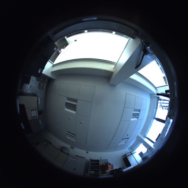
Sample image from ASI174MC and Fukinon FE185C057HA-1 2/3" fisheye lens.
The complete control system is intended to timestamp and watermark images, change the recording cadence according to AuroraWatch UK status and solar elevation, record temperature and humidity, and control heating and fans.


Tuesday, 28 October 2014

FTDI all-in-one serial converter, programmer, switch


FTDI all-in-one
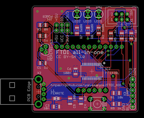
FTDI all-in-one PCB layout.

There are a multitude of FTDI converters and breakout boards available but none of them exactly fitted my needs so this is my version tuned to suit my requirements. I'm publishing the design files in the hope they are useful for others. Like the Sparkfun FTDI Basic Breakout and the Adafruit FTDI Friend it uses the FTDI FT232R but there are a number of differences, for instance it has a USB type A connector to plug directly into a USB host port.

Serial converter

The FTDI AIO provides a serial adaptor with the standard 6 pin FTDI pinout (TX, RX, CTS, DTR, VCC, and GND). A jumper block enables the VCC pin to be switched between +3.3V and +5V. A separate jumper enables the logic levels of the TX, RX, DTR and CTS signals to be set for +3.3V or +5V operation. The Sparkfun FTDI Basic Breakout can also be switched between +3.3V and +5V operation but does not allow for independent selection of VCC and the logic levels. This means when the Sparkfun FTDI Basic is set for +3.3V operation it's not compatible with the standard FTDI cables, which always supply +5V to the VCC pin. Whether that's a good thing or a bad thing depends on your needs; the FTDI AIO gives you both options.

AVR ISP programmer

Programming AVR microcontrollers, even with just a small bootloader, can be painfully slow and normally I'd use the AVR Dragon. There are situations however where it would be useful to have a low-cost USB programmer. A bit-banging AVR programmer is easily made and Adafruit has an excellent tutorial which explains how to do this.The FTDI all-in-one makes this convenient by providing the standard AVR ISP header. The defacto AVR standard is that the VCC pin is set to the same voltage as the logic-level signals. Unfortunately this practice isn't followed by +3.3V Arduino boards which always set VCC to +5V. For the widest compatibility the AVR ISP VCC pin can be set to either +3.3V or +5V with the logic levels of the !RESET, MISO, MOSI and SCK signals independently configured to either  +3.3V or +5V.

On-board +3.3V voltage regulator

One of the features of the FT232R is that it has a built-in +3.3V regulator. This was used by older Arduinos to provide a +3.3V supply. However the current capability is limited to just 50mA which in many cases is not sufficient to power a microcontroller and all of its peripherals. The FTDI all-in-one can include an on-board voltage regulator with 250mA current output which should be sufficient to power an Arduino and several shields.

Auxiliary switch and LED

One of the key features I wanted was the ability to add an auxiliary switch and LED to the Raspberry Pi. Although the Pi has GPIO the AuroraWatchNet magnetometers normally have a radio fitted to this connector, which prevents it being easily used for other purposes. I worked around this by wiring a switch and LED to a Sparkfun FTDI Basic Breakout but I wanted a single PCB which plugged directly into one of the Pi's USB sockets.

Why would you want a switch? There are probably many uses. Mine is that I run one of the AuroraWatchNet magnetometers and I wanted a way to conveniently signal when I am going to cut the grass, or make some other magnetic disturbance in the garden.The data logging software, which runs on a Raspberry Pi, checks for the existence of a file which signals data quality might be bad. When the file is present data is logged to a separate set of files which aren't used by the AuroraWatch UK alerts system. While it's no bother for me to create the file by logging into the Pi I needed something simpler for other members of the family, so I wanted to wire up a switch. A separate daemon monitors the serial port to detect if the switch is pressed, if so the LED is turned on and the semaphore file created. If the switch is pressed again the file is removed and the LED turned off. The LED actually tracks the state of the file being present so it is possible to override the monitor process by creating or removing the semaphore file by other means.

Breakout board

All of the GPIO pins from the FTDI FT232R are conveniently broken out to pads spaced at 0.1" pitch. Also included are pads for the filtered +5V supply obtained from USB and +3.3V from the on-board regulator (if fitted, otherwise from the FT232R's built-in regulator).

Why use the FT232R?

Given the recent controversy regarding FTDI and Windows drivers you might wonder why I am using the FT232R instead of some other device. I'd probably prefer to use the Microchip MCP2200 USB UART converter for this application as it works well with my Calunium Arduino clone and it is available in a SOIC package which is easier to work with at home. Unfortunately its not possible to read the CTS line with the USB CDC driver which rules it out.

Open-source hardware

The Eagle PCB design files are available on Github and are licensed under the Creative Commons Attribution-ShareAlike 3.0 (CC BY-SA 3.0) license.

The PCB layout is not yet tested, although I did breadboard and test all of the functionality. I'll be sending the design off for manufacture in the next few days, it's likely I'll have a few boards spare.

Update: the first boards have been assembled and tested; all features work as planned. The bit-banging AVR ISP programmer is even slower than I feared, taking about 10 minutes to read the 4Kb EEPROM on the Atmel ATmega1284P on one of my Calunium boards.

Friday, 12 September 2014

Why Kp is a poor indicator for auroral alerts

What is Kp?

Kp is a an index to represent the planetary geomagnetic activity. The name originates from "planetarische Kennziffer" (German for planetary index). It has 10 main levels, numbered from 0 (no geomagnetic activity) to 9 (extreme geomagnetic activity). The intermediate ranges are subdivided with a + or - suffix, making 28 levels in total (0, 0+, 1-, 1, 1+, 2-, 2, 2+, ... 8, 8+, 9-, 9).

The Kp index is calculated for three-hourly intervals, beginning at UT midnight. To calculate Kp the daily "solar-quiet" (Sq) variation is removed from the measurements of magnetic field strength. Then the difference between the largest and smallest values is computed. By looking up the difference in a conversion table the local K index can be found. Stations at different latitudes (or more properly magnetic latitudes) have different conversion tables.

There is a pronounced daily variation in the K index at a single station, with intervals close to local midnight being substantially more disturbed in comparison with those centered on local noon; see http://www-app3.gfz-potsdam.de/kp_index/conv_tab.html. For this reason the planetary Kp index is computed from magnetic variations recorded by 13 magnetometers located around the world.

Why Kp is a poor indicator for auroral alerts

The Kp index only indicates geomagnetic activity within a 3 hour interval, which is too long to be useful for auroral alerts. Geomagnetic conditions can have recovered to a calm state long before the next Kp index is computed. This is particularly true for aurora caused by a substorm, as the entire substorm cycle (including the growth, expansion and recovery phases) is typically 2 to 4 hours duration; see http://www.ann-geophys.net/29/2031/2011/angeo-29-2031-2011.html.

It must also be noted that the official Kp values are not available in real-time. Not only must the data from the 13 stations be collected the quiet-day curves for each of the magnetometers must be calculated for that calendar month, a process which cannot begin until the month ends. Therefore any references to Kp for the current month will be to unofficial estimates. The most reliable estimate of Kp is probably obtained from NOAA, which is derived from a worldwide distribution of magnetometers, see http://www.swpc.noaa.gov/products/planetary-k-index.

In summary: Kp is not available in real-time. The 3 hour interval means current auroral activity may be much lower than an estimated Kp value suggests.

Estimated Kp can differ significantly from the local K index

As noted above, the pronounced daily variation of the K index means that there can be considerable difference between the average planetary geomagnetic activity (Kp) and that observed locally (K). The plot below shows the difference between the local K index measured by the British Geological Survey magnetometer at Eskdalemuir and Kp.

Difference between Eskdalemuir local K index and Kp
Difference between K index measured at Eskdalemuir and Kp.

The plot shows that in general there is good agreement but at certain times the K index can be higher or lower than Kp.

In summary: global measurements of Kp are not always valid indications of  regional geomagnetic activity.

What measurements should be used?

One of the better measurements is using the K index as long as it is from a nearby magnetometer or one on a similar geomagnetic longitude. It is still limited by the 3 hour resolution of the K index so it will not always be accurate for real-time measurements.

An alternative measurement is to consider the rate of change of the magnetic field, commonly referred to by its mathematical notation dB/dt ("D B by D T"). This measurement is of particular interest to operators of pipelines and long power distribution networks since it indicates the levels of geomagnetically-induced currents which might be expected. British Geological Survey publish real-time dB/dt measurements. These measurements require magnetically quiet sites as human interference is likely to cause sudden spikes with a high dB/dt value, limiting its usefulness to observatory measurements.

AuroraWatch UK publishes a real-time auroral activity measurement. It is the H component deviation, which is the difference between the current H component magnetic field strength and the expected value for the time of day taken from the "quiet-day curve". Unlike Kp this measurement is computed hourly and so can indicate a return to low activity values sooner than Kp. An accurately fitted quiet day curve is required to make the deviation measurement.

Data credits

Eskdalemuir K indices were downloaded from the British Geological Survey, https://www.bgs.ac.uk/discoverymetadata/13480122.html. Kp data was downloaded from GFZ-Potsdam, ftp://ftp.gfz-potsdam.de/pub/home/obs/kp-ap/tab/.

Saturday, 17 May 2014

Calunium v2.1a

I've made a few minor improvements to the Calunium design, partly to satisfy compatibility between Calunium and Arduino shields and partly to fix a few minor hardware errors.

Disconnect VCC from the ISP header

The ISP header is a 6 pin male header which can be used to program the microcontroller, such as to upload the bootloader. On Calunium the VCC pin of this header is wired to the same supply voltage used by the microcontroller, ie +3.3V or +5V depending upon the operating volatge selected. This makes sense, especially when used when programmers such as Atmel's AVR Dragon which use the pin to set the HIGH voltage level on the SCK and MOSI control lines. Unfortunately it seems that on Arduino devices (such as the Ethernet shield) this pin is always wired to +5V. This is true even for the latest hardware versions which should be aware of the operating voltage via the IOREF pin. To avoid the possibility of connecting the +3.3V and +5V supplies I added a jumper. For normal operation the shunt can be omitted. When using an ISP header programmer that needs to know the operating voltage a shunt can be added.

Pull-down resistor on D13 FET

Calunium uses a field-effect transistor (FET) to switch on the D13 LED. This is to avoid load on the D13 SCK line when it is used for SPI communications. I learnt this trick from Freetronics who do something similar with their range of clones. In normal use, when D13 is an output, everything works fine. However, when it is an input, such as during RESET state or bootloader programming, the FET gate can float to potential such that the LED is switched on. A 1 megaohm pull down resistor connected to D13 is sufficient to prevent this happening without loading the SCK line. It also helps prevent damage by electrostatic discharge. The latest Calunium design now has room to add this 1 megaohm resistor. On older boards an 0805 surface mount resistor can be fitted between the gate and source of the 2N7000 FET, or alternatively between the D13 and adjacent ground pin.

Auto-reset behaviour corrected for MCP2200 USB interface

I recently added the option of fitting the MCP2200 USB-serial interface. Despite suggestions to the contrary this useful USB  device can automatically reset the Arduino when the device is opened. This auto-reset behaviour as it is known is used to activate the bootloader when uploading sketches. The intention was that auto-reset could be disabled by removing a shunt from the AUTO RESET jumper. Unfortunately an error in the schematic meant that auto-reset could only be disabled when using the FTDI interface, not the MCP2200 option. The latest version corrects this error.

Silkscreen label corrected

On Calunium v2.1 a jumper was added to select FTDI or USB power. Due to a rotation of the component the correct position for the shunt is opposite to that indicated by the silkscreen label. The latest version corrects the text.

Open source

The Eagle PCB design files for Calunium are available on Github and are licensed under the Creative Commons Attribution-ShareAlike 3.0 Unported License. Files to allow Calunium to be used with the Arduino 1.0 IDE are available on  Github and are licensed under the Gnu General Public License v2.

Monday, 24 March 2014

Power over ethernet (PoE) magnetometer and cloud detector

Combined magnetometer and cloud detector
Combined magnetometer and cloud detector.


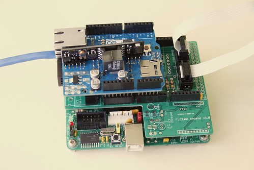
To improve the performance and stability of the AuroraWatchNet magnetometers I recently began experimenting with a power over ethernet (PoE) version. With restrictions on power consumption lifted considerable performance improvements are possible. As a result I have developed the magnetometer hardware specifically to support a power over ethernet version. Another instrument I've been developing is a cloud detector. This too should benefit from a power over ethernet version. One problem I encountered was with dew settling on the sensor but fitting a heater is incompatible with battery-powered operation. Since both the magnetometer and cloud detector use almost the same hardware I decided to design an Arduino-compatible 'shield' that could be used to support both systems.

Combined magnetometer and cloud detector hardware

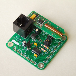
Combined magnetometer and cloud detector PCBs
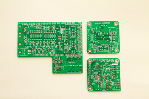
Printed circuit boards for the sensor shield (left), the IR or humidity sensor (top right)
and fluxgate magnetometer (bottom right). Click for annotated version.
The complete system requires six circuit boards (five for the wireless version). The first is the microcontroller board, I use my Calunium Arduino clone. I hope that in future it will be possible to use an off-the-shelf Arduino Mega2560 instead but the current firmware relies on Calunium's real-time clock to generate the hardware interrupts which control the sampling interval. There is also a sensor shield, the Arduino Ethernet shield (omitted on the battery-powered wireless version), and one board for each of the sensors (fluxgate magnetometer, IR temperature and humidity).

The sensor shield is based on the existing design and retains the option of battery-powered operation with radio communication. The magnetometer sensor and analogue-to-digital converter must be powered at 5V, which requires a level-shifting circuit when the microcontroller is powered from 3.3V, which is the case when operating from batteries. For power over ethernet use the microcontroller must also operate at 5V for compatibility with the Arduino Ethernet shield so the level shifting is not required. It is kept however as it provides buffering between the two circuit boards; 1.5m is a considerable distance for an I2C bus. The cloud detector uses a non-contact infra-red temperature sensor operating at 3.3V so a level-shifting circuit is required for PoE operation where the microcontroller is connected to 5V. (I've ignored the fact that a 5V version of the sensor exists since it isn't readily available in the UK). The sensor shield allows a humidity sensor to be connected so that estimates of the clear sky and cloudy sky temperatures can be made. As before, an on-board LM61 temperature sensor monitors the system temperature. The new sensor shield also adds a header to fit an Embedded Adventures lightning sensor module. I don't have one of these at the moment so I can't be certain it will work and there is no software support for it in the existing firmware. Fitting it at the same time as the cloud detector sensors will require long break-away headers to be soldered to the bottom of the lightning sensor module.

Fluxgate magnetometer sensor PCB
Fluxgate magnetometer sensor mounted on its sensor PCB.
Click for annotated version.

The fluxgate sensor is fitted on its own PCB which contains the analogue to digital converter. For PoE operation a linear voltage regulator is used to convert from 9V to the 5V supply it requires. For battery operation a MAX619 DC-DC charge pump boosts the battery voltage to 5V. Almost all of the temperature variation can be removed by placing the PCB at the bottom of a 1m length of soil pipe. The pipe is buried to a depth of 0.85m with its axis vertical. In the magnetometer-only system the microcontroller, sensor shield and ethernet shield (or batteries for the wireless version) are fitted onto a wooden frame to hold them into the top part of the tube. Positioning the rest of the system away from the fluxgate sensor helps to avoid unwanted effects from any ferro-magnetic components (such as the batteries), it also aids access and enables wireless data transmission.

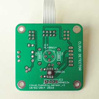
Humidity sensor PCB
Honeywell HIH6131 humidity sensor mounte on its sensor PCB.
The same PCB design is also used for the MLX90614 IR temperature sensor.
Click for annotated version.

The enclosure design used for the magnetometer isn't suitable for the cloud detector so the prototype cloud detector used a standard IP65 rated box, with the IR temperature sensor pointing upwards to view the sky. The humidity sensor was fitted above a breather hole in the bottom of the box. This concept will continue to be used for the cloud detector; the IR temperature sensor and humidity sensor are fitted to separate PCBs in the top and bottom of the box. To minimise costs the IR temperature and humidity sensors use the same PCB design. The mechanical design of the cloud detector part is something I'd like to improve upon, particularly to reduce the number of PCBs used. However the differing sensor requirements may prevent this.

For a combined system I plan to use the soil pipe to house the fluxgate sensor but locate the rest of the electronics in a separate box following the design of the prototype cloud detector.

Does it work?

I've not yet deployed a system outside but testing indicates the new printed circuit boards work as intended when used in power over ethernet mode. Battery-powered operation on this new version has not yet been tested.

Design files

The design files (hardware, firmware and software) are open source and can all be downloaded from the Github repository. A PDF version of the user manual describing how to construct and operate the magnetometer can be downloaded from http://aurorawatch.lancs.ac.uk/manual.pdf. At the time of writing only instructions to build the original FLC100 shield are included. Instructions to build the combined sensor shield described above will be added in due course.


Wednesday, 12 February 2014

Performance comparison of power over ethernet (PoE) and battery magnetometers

Introduction

I've been working to improve the performance and stability of the AuroraWatchNet magnetometers. It's apparent that both measurement noise and stability are considerably improved when the sensor is powered continually. Unfortunately with the sensor powered continually the batteries last for only a few weeks. I have therefore been testing a power over ethernet (PoE) version of the magnetometer. The hardware is essentially the same but the addition of the Arduino Ethernet shield requires the microcontroller to operate from 5V. Operating voltage is easily changed on my Calunium microcontroller board. With the power restrictions lifted the sampling interval can also be reduced. The test system has been operating reliably for almost two months, sampling every 5 seconds. With some minor configuration changes sampling every second is possible although I am not convinced the trade-off in measurement noise is worthwhile.

Performance comparison

Below is a plot comparing one hour of data from the new power over ethernet system with two of the existing battery-powered wireless models already in operation. The PoE system is on the same site as LAN1 but located nearer parked cars. I chose this period because it was free of man-made disturbances. I adjusted the baselines so that the plots overlap.Only the H component of the magnetic field is shown.

Power over ethernet compared with existing AWN magnetometers
Click for larger version.

The graph shows that the power over ethernet version has much smaller measurement errors; it can probably operate with ~0.1nT accuracy compared to ~10nT for the battery-powered version. It's such an improvement that I found the measurement accuracy was being limited by the available resolution of the analogue-to-digital converter. The battery-powered versions derive the sample value from the median of 15 samples (taken as a burst over 4 seconds) to reduce noise. To improve the resolution for the PoE version it operates by taking the mean of 15 samples. Further improvement to the resolution may be possible by taking advantage of the programmable gain amplifier that is built into the analogue-to-digital converter.

Let's see how it compares against some observatory-grade measurements. The plot below shows the same interval but this time uses data from the British Geological Survey magnetometers at Eskdalemuir and Hartland. I obtained the data from the SAMNET data archive at Lancaster University, where the data has already been converted into HEZ magnetic coordinates. AuroraWatchNet also operates with HEZ magnetic coordinates, although usually the E and Z sensors are not present. As before, the baselines have been adjusted so that the plots overlap.


PoE magnetometer compared with BGS magnetometers
Click for larger version.


The similarity between the different traces is striking. Some differences are to be expected since Eskdalemuir is approximately 140km north of Lancaster and Hartland is 350km SSW of Lancaster. This interval is interesting because it shows Pi2 pulsations, starting at about 01:15 and ending around 01:30. The period of the pulsations are about 90 to 120 seconds.

Conclusions

For a home-built citizen-science magnetometer which probably costs 25 times less than its observatory grade cousin I'm very happy with its performance. The detection of Pi2 pulsations means a low-cost magnetometer can now notify of substorm onset, not just the arrival of geomagnetic storms. A network of such devices has interesting possibilities for the study of magnetic field line resonances.

You might wonder why anyone would want to buy an observatory grade instrument, there are good reasons. At present I am relying on the sensor manufacturer's calibration, whilst an observatory grade instrument would be supplied with an official calibration certificate. The observatory instrument would also have better long-term baseline stability, lower temperature variation and higher cadence. Calibration is an issue I hope to tackle at a later date. For space-weather monitoring only short-term variations are of interest and
the better performance provided by an observatory system may not be needed.

Data credits

The Sub-Auroral Magnetometer Network data (SAMNET) is operated by the Space Plasma Environment and Radio Science (SPEARS) group, Department of Physics, Lancaster University. Hartland and Eskdalemuir data is provided courtesy of the British Geological Survey.


Sunday, 27 October 2013

Magnetometer progress report: link indicator LED

I recently added a new feature to the magnetometer remote sensor unit firmware. To help indicate when it is within radio communication range of the base unit an LED is turned on at the start of a message communication. When the sensor unit receives the acknowledgement from the base unit of successful message receipt the LED is switched off. In normal operation the LED should blink briefly every 30 seconds, after each sampling interval. If the LED remains on it indicates a problem with the radio link. For the initial installation the sampling time can be reduced to 5 seconds for to obtain faster feedback of whether communication is successful or not.

Improvements for battery-powered operation

Indicating link errors by using an LED is convenient during installation but the power wasted after installation is not compatible with battery-powered operation. To save power the LED is used only the first 15 minutes of operation. Only user-initiated reset actions (power on or reset switch pressed) cause the LED to be used, resets from by the watchdog timer or brown-out detector are ignored. The cause of the reset is detected by examining the microcontroller's status register (MCUSR).


Communication timeout feature added

I've also added a timeout which detects when communication has been lost for an extended period. The microcontroller system is rebooted in the hope that the error is recoverable. Loss of communication, along with low battery status, can also be sensed and reported by running the latest version of the data plotting software on the Raspberry Pi. If either error is detected a message can be sent via email, Twitter or Facebook.


Saturday, 19 October 2013

Cloud detector: a review of progress so far

The hardware

My cloud detector has been running outside for over 5 months now. Overall I'm very pleased with how it works. The battery-powered hardware is based on the AuroraWatchNet magnetometer design, which uses my own Calunium microcontroller development board. The remote sensor board and fluxgate sensor are omitted. I've added a Melexis MLX90614 non-contact infra-red thermometer to measure the sky temperature. Clear skies should give low temperatures whilst clouds are expected to have warmer temperatures, although still colder than the ambient temperature. The MLX90614 also outputs the sensor temperature, which should be close to the ambient temperature. I also added a Honeywell HIH-6131-021 humidity sensor which has an I2C interface. Do not confuse with the similar sounding version which has an SPI interface! The HIH-6130 also provides and ambient temperature measurement. To avoid direct contact with water the humidity sensor is placed at the bottom of the enclosure with a hole underneath to expose it to air. This hole also functions as a breather hole and ensures that the internal pressure matches atmospheric pressure. Since this hole was drilled there have not been any more incidents of water ingress.

The Calunium board is running a firmware is a modified version of the magnetometer firmware. It communicates with the Raspberry Pi data logger using an 868MHz radio link, with the same signed communication protocol used by AuroraWatchNet. This means I can use the data recording software from AuroraWatchNet. It also inherits the signed over-the-air firmware update capability. In principle it should be possible to combine both magnetometer and cloud detector functions in one unit.

I started off using the 90°  field-of-view version of the non-contact IR thermometer but later switched to theMLX90614ESF-DCH-000-TU-ND variant which features a 12° field of view. Its greater height meant it was easier to fit into the cable grommet housing. However I think the FOV is too narrow and I plan to switch back to the original sensor when I have time.

Data processing

The data processing and plotting now uses the auroraplot library for Python, which I developed to process the AuroraWatchNet magnetometer data. On the graphs I plot the sky temperature measured by the non-contact IR thermometer and the ambient temperature measured by the humidity sensor. For monitoring purposes I also plot the sensor temperature of the IR thermometer (marked as "detector temperature"); this should be similar to the ambient temperature but its exposed position makes it more likely to undergo solar heating and radiative cooling. For good measure I also plot the system temperature, which is measured by an LM61 temperature sensor connected to the ATmega1284P's analogue to digital converter. This measurement is noisy but useful to check the system doesn't overheat on sunny summer days.

The plan is to estimate the upper and lower bounds that I would expect for the sky temperature, and from that derive an estimate of the cloud cover. I initially expected that with complete cloud cover the sky temperature would match that the lifted condensation level, which I estimate using the ambient temperature and relative humidity. I soon saw temperatures higher than the LCL temperature. Research literature indicates that the clouds can act as a mirror at long IR wavelengths and thus the expected temperature should include an effect of ground temperature too. On the plots this is shown as the effective cloud temperature. The clear sky temperature is derived from results found in research literature but none of the equations tried so far have been a great match. Other researchers have fitted parameters for their specific location (including altitude) by comparison with visual measurements. I have yet to try this but daily measurements are made at the nearby Hazelrigg Weather Station. The graphs are too cluttered for production use but help me to understand what is happening.

Example plots

Below are a selection of plots. You can see the entire archive (from 2013-07-14) at http://aurorawatch.lancs.ac.uk/testing/cloudwatch/test2/.

cloud_detector_20130903
Cloud detector data for 2013-09-03. The asterisk (*) indicates derived parameters (ie not directly measured).
The figure above include most of the effects that can be identified. After midnight there is thick cloud, which later clears for short periods. At around 0300 UT I think it must have rained, the sky temperature is almost identical to the detector temperature and the variability is much reduced. Whilst the sensor is wet no sensible conclusions about cloud cover can be drawn. At about 0700 UT the sensor clears of water and the sky temperature falls indicating clearer skies. The rest of the day is dry, with heavy cloud cover until 1400 UT. At around 1700 UT the skies are completely clear. The clear sky estimate is too low for this time. At 2000 UT the clouds return, with some clear patches.


Cloud detector, 2013-09-28
Cloud detector data for 2013-09-28 showing the effect of clear skies.
The figure above shows an almost completely cloud-free day. The higher variability in the sky temperature measurements between 1200-1600 UT corresponds to similar effects in the humidity data (shown below); both are direct measurements made by different sensors.

Relative humidity, 2013-09-28
Humidity data for 2013-09-28. Notice how the higher variability occurs at the same times as the sky temperature measurements.

Dew

During summer operation dew has not been a problem but now that the nights are colder I have noticed effects which I believe are due to the formation of dew on the sensor. In the first plot below the sky temperature apparently rises from around 2230 UT. The rise is smooth and during this period the ambient temperature is falling, which overnight is often a sign of clear skies. After midnight (second plot) the sky temperature increases slightly before falling sharply around 0630 UT. Sunrise on this day was 0622 UT.

Cloud detector, 2013-10-05Cloud detector, 2013-10-06
This pair of plots is believed to show dew formation on the sensor.


Conclusions

I know from the informal comparisons with visual cloud cover that I regularly make the cloud detector does generally work very well. It does not function during wet periods. As anticipated dew is becoming a problem during the colder nights and a dew heater will be required for reliable winter operation. Future development will be to add a heater, which will need a wired connection to the cloud detector. Once a wired connection is made the radio link appears superfluous so I plan to investigate the options for power-over-ethernet. The Arduino ethernet shield is one possibility, although its compatibility with 3.3V operation has not been established.

Thursday, 26 September 2013

Auroraplot: data processing software for AuroraWatchNet

With the dispatch of the AuroraWatch schools' magnetometers imminent I have implemented a  Python  toolkit to process the data. The numpy and matplotlib modules are used extensively. The toolkit provides an API to load data and perform various processing actions on it, such as plotting data. The concept is influenced by my previous Multi-instrument Analysis toolbox for Matlab. In addition to the loading and processing of magnetic field data auroraplot allows other data types to be added later.

Loading data

Data can be loaded with arbitrary start and end times very simply:

md = ap.load_data('AURORAWATCHNET', 'LAN1', 'MagData',
                  np.datetime64('2013-09-20T12:00:00+0000'),
                  np.datetime64('2013-09-21T12:00:00+0000'))


In this case the selected portion of data crosses midnight and two data files must be loaded, concatenated and trimmed to get the desired time range. This is performed automatically by auroraplot, the user need not be concerned with the format of the files or where they are located. It is even possible for the files to be downloaded on-the-fly using FTP or HTTP transfer protocols.

load_data returns an object (of type MagData) to the user containing the actual magnetic field data and various other metadata, such as a timestamp for each sample and the data units. Each object can store more multiple data channels but all data points must share the same timestamps, be of the same type and share the same units. Therefore it is not possible to store operating temperatures (units °C) in an object holding magnetic field strength (units tesla). The operating temperature data can be accessed as:

td = ap.load_data('AURORAWATCHNET', 'LAN1', 'TemperatureData',
                  np.datetime64('2013-09-20T12:00:00+0000'),
                  np.datetime64('2013-09-21T12:00:00+0000'))


Battery voltage (data type VoltageData) can be accessed in a similar same way.

Plotting data

High-level plot functions enable the data be be plotted very simply, for the magnetic field data loaded previously

md.plot()


will produce a matplotlib figure with a title and the axes labelled with the correct units. Temperature and voltage data are plotted in the same way.

I have created some tools to make working with numpy's datetime64 and timedelta64 objects more convenient, including rounding functions (round, ceil and floor) which round to an interval. They are useful for finding the start of an hour, or the end of a day. I have also created Locator and Formatter classes to sensibly label time axes using datetime64 times and timedelta64 intervals. Tick marks are located on the nearest second, minute, hour, day, month or year boundary (or multiple thereof) depending on the time interval being displayed. Thanks to matplotlib's structure the labels are automatically regenerated with the most appropriate time units when a plot is zoomed.

Other operations

Quiet-day curves

Other operations include the generation of quiet-day curves. These are the curves from which we measure geomagnetic activity and are of critical importance for AuroraWatch UK. There are are not flat but have a daily variation caused by the equatorial electrojet. The empirical algorithm selects the days (typically 5) with the least geomagnetic activity. A truncated Fourier series is used to guarantee that the quiet-day curves are cyclic, with the start and end points having the same magnitude and slope. This is essential otherwise our rolling plots would show up the discontinuities in the QDC at midnight, and would falsely cause step changes in the geomagnetic activity. An example QDC is shown below.

qdc
Quiet-day curve for magnetometer at Lancaster ,UK. This is derived from recorded data
and clearly shows the Sq current system caused by the equatorial electrojet.

From this we can see that even on a geomagnetically quiet day we would expect a 30nT variation in field strength seen by the magnetometer. The AuroraWatch threshold for minor geomagnetic activity is 50nT so this shows the importance of using a quiet-day curve instead of a flat line when calculating geomagnetic activity.

Stack plots

Stack plots (also called magnetograms) are a convenient representation for magnetic field data from a set of magnetometers separated in latitude.Data from the northernmost instruments is placed at the top and that from the southernmost at the bottom. An example stackplot is shown below:

20130920
Stackplot showing data from two Lancaster stations and from Ormskirk.
The magnetometer at Ormskirk is operated by the Met Office as part of a test. The stackplots will be more interesting as the network grows.

Open source

The source code is available under a BSD-type license from Github.You will need python, along with the numpy (version 1.7), matplotlib and scipy python modules.auroraplot has been tested under Debian Linux (64 bit version) and Raspbian on the Raspberry Pi.


Thursday, 8 August 2013

Securing your SSH server against brute force password attacks

If you run an SSH server open to the whole internet you'll soon notice many attempts to break into your system using random username and password combinations. This 'noise' in the log files is annoying and might mean you miss an important message. If you are unlucky or use a common username and password your system might be compromised by one of these brute force attacks.

One method to drastically reduce the number of cracking attempts is to restrict access to the SSH server by IP address. This can done be done either by editing the SSH config file or by using configuring iptables. However this method requires valid users to have static IP addresses, something which most home users don't have. In many cases public key authentication is a better choice.

Use public key authentication

A better method to stop attackers from using random username and passwords is to switch off password authentication entirely and require public key authentication instead. Attackers will not be able to try random username/password combinations and will not create 'noise' in the log files. Valid users will still be able to connect.

To describe how this can be set up assume we wish to protect a computer with a static IP address called server. We wish to access it from another system called laptop, (which may be using a dynamic IP address). The account on server that we will access is dave. We'll assume that the SSH configuration file is /etc/ssh/sshd_config. Adjust these names to suit your setup.

Firstly, on laptop create a public/private key pair.
ssh-keygen -t dsa

A passphrase is not required although it is a good idea. On server make sure a ~/.ssh directory exists with the correct permissions:
mkdir ~dave/.ssh
chmod go= ~dave/.ssh

Using your favourite editor (emacs of course) paste the contents of the public key into the ~dave/.ssh/authorized_keys file on server. Putty users may find the instructions at http://www.howtoforge.com/ssh_key_based_logins_putty helpful. Check that you can log into server without requiring your password. If you are going to configure server remotely ensure you can log in without needing your password, otherwise you will lock yourself out! If you set a passphrase you will need to type that.

Configure the server

The key requirement for the server configuration is that by default password authentication is turned off. Find the line in /etc/ssh/sshd_config which sets password authentication. Make sure it is set to
PasswordAuthentication no
If necessary remove any leading # character. Whilst editting /etc/ssh/sshd_config its a good idea to disable empty passwords and root logins, ensure the following lines are set
PermitEmptyPasswords no
PermitRootLogin no
If you need empty passwords or root logins from specific hosts this can be overridden later.


Enable password authentication for trusted hosts

Once password authentication is disabled users on a multi-user system will have a problems copying their keys to grant them access! Exceptions can be made for trusted static IP addresses so that users can copy their public key. Assume we trust all IP addresses in the subnet 192.168.1.0/24. Passwords can then be enabled by simply adding the following lines to the end of /etc/ssh/sshd_config
Match Address 192.168.1.0/24
PasswordAuthentication yes

Enable root logins

Suppose a root login using password authentication is required for one host only (192.168.1.123). Add the following lines to /etc/ssh/sshd_config
Match Address 192.168.1.123
PasswordAuthentication yes
PermitRootLogin yes

Summary

These simple steps keep your SSH server accessible from everywhere but greatly reduce the likelihood of a successful brute force attack. The Match keyword requires openssh version 4.4 or later.

Thursday, 30 May 2013

Cloud detector: first data

Annotated plot for 2013-05-30.
The cloud detector has been operating outside for a few days now. The plot above is an example of the data I am getting, annotations added manually! The ambient temperature is the temperature of the sensor. In reality this may be a little warmer than ambient when it is exposed to direct sunlight. The sky temperature is the object temperature from the sensor. It is an average over its field of view, and in the absence of clouds it is also averaged in height. From the plot a number of features can be identified:

Clear sky
With no clouds to reflect back thermal radiation the sky temperature for a clear sky is very low, typically < -10°C. This results in a large difference (> 20°C) between ambient and sky temperatures.


Overcast sky
With the presence of clouds most thermal radiation is not lost to space but reflected back to Earth and the sensor. The difference between ambient and sky temperatures is small (< 10°C). With a uniform cloud coverage the variation in the difference is small.


Cloudy sky
A sky with partial cloud cover has an intermediate difference in ambient and sky temperatures. The cumulus clouds resulted in a large variation of the temperature difference, caused by the more sensitive central viewing area observing alternately clear sky and cloud. Complete coverage by a thin layer of cloud is expected to give an intermediate temperature difference but low variability.


Wet sensor
When the sensor is wet with rain the sky temperature is measured incorrectly since the water is not transparent to long-wave infra-red radiation and matches the ambient temperature. As wet weather implies cloud this is not a major problem although I have concerns over the time taken for the sensor to dry off.


Dew
The formation of dew is observed in the evening as the ambient temperature falls. The difference between ambient and sky temperature is reduced to less than 10°C.

Future work

Early operation shows that dew is a problem and can indicate cloud when the sky is actually clear. I have considered creative solutions such as painting the top of the box white and the bottom black in order to minimise heat lost to the sky and maximise heat absorbed from the ground. I expect this will only delay the onset when dew becomes a problem, not eliminate it. The only viable solution is to heat the sensor slightly (~2°C) above ambient, which means moving away from battery-powered operation. If a cable is used for power then wireless communications makes little sense, power-over-ethernet seems the way forward. A heated sensor will also reduce the drying time after rainfall.

I still have some concerns regarding waterproofing around the sensor. I have ordered the MLX90614ESF-DCH-000-TU-ND which features a 12° field of view. This narrower view is obtained by fitting a refractive germanium lens above the sensor. The TO-39 package has been modified to be taller than standard to accommodate the lens. The additional height should mean that the top of the sensor is above the cable gland. Water should not collect so easily and it should be possible to use silicone sealant without accidentally coating the sensor window.

Previously I tried pointing the sensor downwards and using a metal surface as a mirror to view the sky. The experiment was not successful and I think this was in part due to the wide field of  view of the sensor (90°) preventing a clear upward view without also observing the ground or enclosure. It will be worthwhile repeating the experiment with the narrow field of view sensor.

I only have basic plotting routines at present. The goal is to produce a cloud cover index, varying between 0 indicating no cloud and 1 indicating complete cloud cover. The index will be used as the basis for sending alerts.


Monday, 20 May 2013

Cloud detector progress

Microcontroller and radio communications

To minimise the time and effort required to test the cloud detector concept I am following the approach used for the AuroraWatchNet magnetometer system and reusing as much hardware from it as possible. The MLX90614 non-contact infra-red temperature sensor is located outside. To minimise the infrastructure requirements the sensor unit is battery-powered and transmits its data over a bi-directional radio link. The sensor is controlled by one of my Calunium v2 microcontroller development boards. I'm using a pair of RFM12B radio modules operating at 433MHz to emulate a transparent serial connection. One is fitted on  the Calunium board and the other radio module is connected to a Raspberry Pi via my RFM12B shield. The Pi records the data and is responsible for uploading it for general access. I am also reusing most of the AuroraWatchNet firmware, which means I already have signed data communications and the capability to deploy over-the-air firmware updates - quite a good starting position for a new project!

Waterproofing the sensor

The biggest challenge I expect to face with this project is waterproofing the sensor. Although it is hermetically sealed there is no easy way to deploy it outside. As explained in a previous post, only a few materials are transparent to long-wave infra-red emissions and the better ones are toxic, water-soluble or expensive. I am therefore trying to avoid covering the sensor window and instead keep the electrical contacts dry. My first attempt was to drill a hole in the box and attach the sensor with silicone sealant. The mechanical fixing lacked strength and I wasn't convinced I had completely sealed around the sensor. To make matters worse I ended up with sealant on the sensor window which had to be cleaned off before it set. Another approach was required.

The new approach is to fit the sensor inside a cable gland. Before doing so I had to attach wires to the sensor connectors and insulate with heat-shrink sleeving. The result is shown below.


The next step is to fit the sensor in the cable gland before fitting the cable gland to the box.


The other end of the wires can then be soldered. For the prototype the wires are soldered to a small piece of stripboard. The stripboard has two pull-up resistors for the I2C bus and a decoupling capacitor. There is also an IDC connector to link the board to the unused JTAG interface. This was the easiest way to connect to a stock Calunium v2 board. For the lowest power operation the sensor is powered from logic-level output and I am using software I2C so all connections can be grounded when the sensor is not in use. The real-time clock on Calunium is connected the the hardware I2C interface on the microntroller and can be operated independently of the sensor.


The box and cable gland are rated IP65. Hopefully the result will be waterproof  

Results

The sensor is now deployed outside and reporting back to the Raspberry Pi base station. The transmitted packets are logged by the Raspberry Pi but as yet I don't have a convenient way to extract the ambient and object temperatures for analysis. That is the next task.


Saturday, 18 May 2013

An open-access cloud-detection network

Introduction

Living in the North-West of England I find that my attempts to view the aurora or astronomical events such as meteor showers, lunar eclipses and comets are often prevented by cloud. On these occasions I wonder if it is worthwhile driving somewhere to find some clear sky. But where? If only I could look at a map to see where it was clear now. Publicly-available satellite images don't appear to have the resolution needed for this purpose. Maybe I should go to bed instead and wait for an alert when the skies have cleared? Could the question of where and when to find clear skies be answered by an open-access cloud detection network operated by citizen-science volunteers?

Requirements

I've together a draft list of requirements to construct a useful network:

  • Open-access. While my primary concern is with viewing the aurora I can see there are many other uses of such a network. Astronomy and obviously meteorology. Open-access enables other observers to make use of the data for their own purposes.
  • Near real-time. The weather here can quickly change. Ideally measurements should be taken every few minutes and be made available without unnecessary delay.
  • Use open-source hardware (OSHW). More specifically, an OSHW design should exist which allows users to contribute readings with the lowest possible cost.
  • Large geographical coverage. 
  • Night time operation required, day time beneficial.
The most difficult requirement to satisfy is the coverage. With ground-based sensors the viewing area might be as small as 2km diameter (cloud-base 1000m, optical viewing angle ±45°); at this size complete coverage of Great Britain would require over 57000 installations. A useful network does not require complete coverage, for auroral and astronomical purposes good results could be achieved by positioning sensors in a few viewing locations selected for low light pollution.

Remotely-sensing clouds

Perhaps the simplest method to remotely-sense cloud cover is to measure the 'sky' temperature with a non-contact infra-red (IR) thermometer. In the absence of cloud cover this is very low (say -12 to -20°C for Spring in the UK) but with cloud cover the temperature measured is warmer (0 to 4°C). These temperatures vary over the course of the year but by looking at the difference between the sky and ambient ground-level temperatures an estimate of cloud cover is possible. Some of these thermopile sensors have a digital output for interfacing directly with a microcontroller.

A camera and image-recognition software is another approach but it is more complex to develop, install and operate. It is not clear how such a system would perform at night. In order to install the maximum number of sensors I plan to concentrate on cheaper methods.

Design concept

I believe there are two key factors which limit the number of sensors in the network: cost and ease of installation. To minimise the infrastructure I plan to begin with a battery-powered unit which communicates with a Raspberry Pi (or other computer) via a low-cost, licence-free radio module. This is the same concept used by the AuroraWatchNet magnetometer sensors.


Potential problems

Precipitation (rain, snow, hail) and dew on the sensor will prevent accurate sky temperature measurements, most likely indicating cloud when it may in fact be clear. A heater to prevent dew forming is an option but the temperature gradients may cause the thermopile to give incorrect measurements. The power consumption needed is incompatible with battery operation. It may be possible to point the sensor downwards, to avoid precipitation and dew, and use a reflective metal surface to observe the sky. Tests shows the sky temperature readings are partially compromised by this approach.


Sensor

I have found a number of sensors which may be suitable:
  • Melexis MLX90614. This sensor contains thermopiles for sensing both the object and ambient temperature. An SMBus interface enables direct connection to a microcontroller. It is packaged in a TO-39 metal can. The standard 3.3V operation, 90° field of view (FOV) variant is readily available in single quantities from UK hobby electronics stores for around £15 each. Other variants exist for 5V operation and with different fields of view (10°, 35°, and a dual 70° FOV). The minimum object temperature is -70°C. The only irritation is that the sleep mode requirements are not compatible with low-power operation on a I2C bus.
  • Melexis MLX90615. Similar to the MLX90614 but the sleep mode requirements are compatible with low-power operation on an I2C bus. Cost is similar to MLX90614 but no UK supplier exists. Package is a TO-46 metal can. Limited to 3.3V operation and a single FOV (80° or 100° variants). The minimum object temperature is -40°C.
  • Texas Instruments TMP006. Small thermopile with I2C interface for direct connection to a microcontroller. Ball-grid array package. Readily available from UK suppliers. Cost is around £3 each for single quantities.
  • Thermometrics ZTP-135SR. Thermopile with analogue output in a TO-46 package, with a thermistor for ambient temperature measurement. Being an analogue output additional processing is required. Around £10 from Farnell.
  • Devantech TPA81. Linear array of 8 thermopiles. Cost is around £65.
  • Panasonic AMG88 Grid-EYE. An 8×8 imaging sensor in a surface-mount package. The minimum object temperature is -40°C. Available from Digikey for around $40.
For the prototype system I plan to use the Melexis MLX90614 sensor. It should be possible to work around the problems with low-power operation by using software I2C and powering the sensor from a logic output, allowing power to be completely removed when not in use.

I excluded the TMP006 because the BGA package is hard to work with; not only is it difficult to solder it will require some kind of enclosure or window to protect it from moisture. Only a few materials are transparent to long-wave infra-red emissions and the better ones are toxic, water-soluble or expensive. The other sensors may be suitable but are more expensive. The TPA-81 linear array and Grid-EYE imaging sensor could provide spatial discrimination and thus distinguish between a thin layer of complete cloud cover and denser clouds with open areas of sky.

Initial results

Initial tests with the Melexis MLX90614 sensor confirm the concept is viable. I have not noticed any ill-effects from the sun within the field of view, suggesting that daytime operation is possible. Further work is required to package the system into a usable prototype which can be deployed outside permanently. Full-time operation will indicate the frequency of measurement errors from dew and precipitation.

Other work

It would be wrong to suggest I am the first to make measurements of cloud cover in this way, useful links are listed below. I am not aware of any existing cloud detection networks.

Useful code for interfacing the MLX90614 IR thermometer with an Arduino. This code works with my Calunium Arduino clone.

Good background information.

http://kcotar.org/arduino-weather-station-1/
A weather station which uses the Melexis MLX90614 sensor for cloud detection.

http://www.noao.edu/staff/gillespie/projects/cloud-detector.html
Similar in concept but using a Peltier device (in reverse) to measure the difference between ambient ground temperature and sky temperature.


Tuesday, 12 March 2013

How to use the GPIO version of avrdude on the Raspberry Pi

Introduction

I previously showed an implementation of a AVR ISP programmer using the Raspberry Pi GPIO port which can be used to program Atmel's AVR range of microcontrollers with avrdude. An ISP programmer based on this design was incorporated into a shield to interface to the RFM12B radio module. This post explains how to use avrdude to actually program devices.

Software installation

Download the patched version of avrdude from http://project-downloads.drogon.net/files/. I also keep a copy in the RPi_RFM12B_ISP respository, https://github.com/stevemarple/RPi_RFM12B_ISP/tree/master/software/avrdude. You will probably want the armhf (hardware floating-point) version. Download the documentation package for avrdude too. Install the packages using "dpkg -i". For example

sudo dpkg -i avrdude_5.10-4_armhf.deb
sudo dpkg -i avrdude-doc_5.10-4_all.deb

Using avrdude over the GPIO interface is problematic for users other than root. The easiest solution is to give the avrdude binary setgroup permission:
sudo chmod g+s /usr/bin/avrdude

Usage

Selecting the GPIO programmer is simply a matter of including "-P gpio -c gpio" options; the -P option specifies that the GPIO port is used (as opposed to USB, serial or parallel interfaces) whilst the -c option selects the correct programmer type on that port.

For example, to check the signature on an ATmega328P execute the command
avrdude -P gpio -c gpio -p atmega328p

To read the fuses execute the command
avrdude -P gpio -c gpio -p atmega328 -U lfuse:r:-:h -U hfuse:r:-:h -U efuse:r:-:h

Customisation

The packages above define a single programmer called gpio which uses the gpio interface on GPIO pins 8 to 11. Since the RFM12B shield for Raspberry Pi implements two independent programmers I prefer to use gpio0 and gpio1. You can add these by creating a .avrduderc file in your home directory. The file should contain:

programmer
  id    = "gpio0";
  desc  = "Use sysfs interface to bitbang GPIO lines";
  type  = gpio;
  reset = 8;
  sck   = 11;
  mosi  = 10;
  miso  = 9;
;

programmer
  id    = "gpio1";
  desc  = "Use sysfs interface to bitbang GPIO lines";
  type  = gpio;
  reset = 7;
  sck   = 11;
  mosi  = 10;
  miso  = 9;
;

Sunday, 3 March 2013

Three-axis sensor unit for AuroraWatchNet

Three-axis magnetometer sensor unit
Three-axis sensor unit. The RJ-45 connector is for power and I2C data signals, not Ethernet.

AuroraWatchNet is a network of magnetometers for auroral alerts and citizen science. Whilst the  magnetometer is intended to function with one single-axis FLC100 sensor from Stefan-Mayer Instruments I have designed the system to support 3-axis operation by mounting 3 sensor boards at 90° to each other using just standard right-angle PCB connectors. This approach avoids the requirement for external mounting hardware which would be expensive to manufacture.

The power supply (a charge-pump DC-DC converter), temperature sensor and RJ-45 connector are fitted to just one circuit board. It is possible to use only one analogue-to-digital converter (ADC) but given their low cost it was presumed they would be fitted to all boards to enable simultaneous sampling of all 3 axes. The MCP3424 converter was chosen because eight options are available for the I2C address, thus jumpers can be fitted to select a unique address for every ADC on the I2C bus. This converter also features 4 input channels. All magnetometer outputs and the temperature sensor are connected to each ADC so that the spare channels can provide some redundancy in case of an ADC failure. The SYNC connectors of all sensors are linked to synchronise their excitation frequencies.

Several single-axis units have been built and one is in active use by AuroraWatch UK. The photograph above shows the first three-axis unit to be built. Initial testing indicates it functions as intended but the performance of 3 simultaneously-powered sensors in close proximity is yet to be established.